HW6 Solutions
advertisement
HOMEWORK 6 SOLUTION MANUAL
Marat K
Problem 1 (5 points):
The Bernoulli equation is:
1
1
𝑃1 + 𝜌𝑉12 = 𝑃2 + 𝜌𝑉22
2
2
Eq1
Since the velocity at the stagnation point is zero and maximum pressure is found at locations with
minimum velocity we should rewrite the Bernoulli equation as:
1
𝑃𝑔𝑎𝑢𝑔𝑒 = 𝑃2 − 𝑃1 = 𝜌(𝑉12 )
2
Eq2
1
𝑘𝑔
𝑚 2
(1.23 3 ) (100 ) = 6150 𝑃𝑎 𝑔𝑎𝑢𝑔𝑒
2
𝑚
𝑠
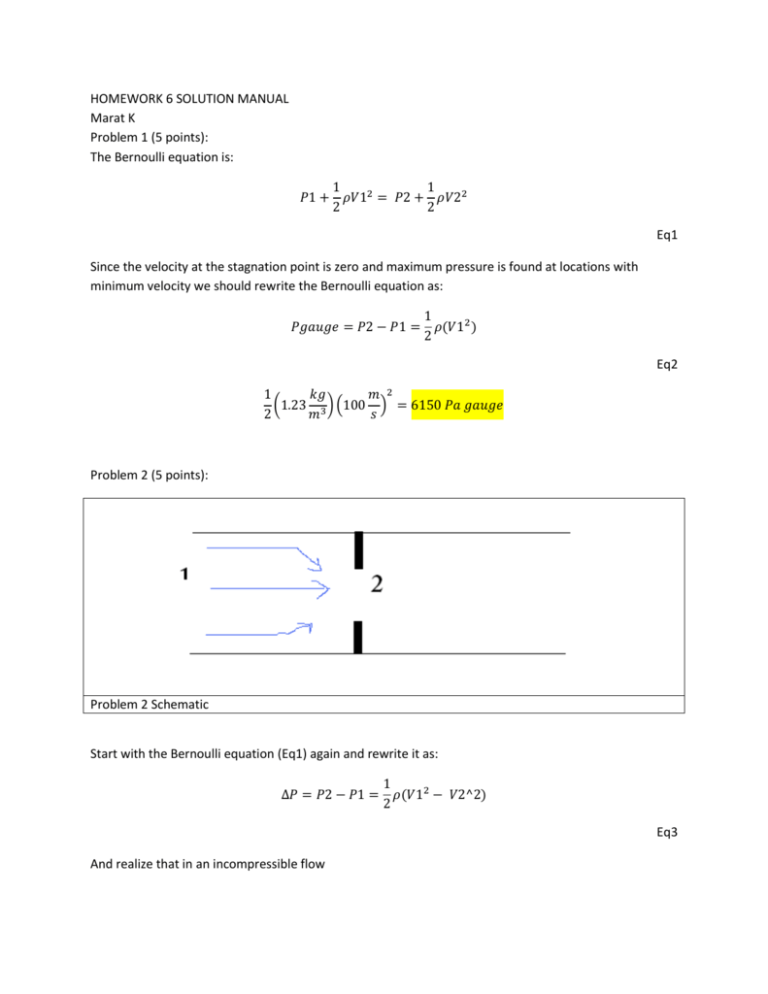
Problem 2 (5 points):
Problem 2 Schematic
Start with the Bernoulli equation (Eq1) again and rewrite it as:
1
Δ𝑃 = 𝑃2 − 𝑃1 = 𝜌(𝑉12 − 𝑉2^2)
2
Eq3
And realize that in an incompressible flow
𝑄1 = 𝑉1 𝐴1 = 𝑉2 𝐴2 = 𝑄2 = Q
Eq4
Combining Eq3 with Eq4 will yield Eq5
𝑄2 𝑄2
2Δ𝑃 = 𝜌 (
−
)
𝐴1
𝐴2
Eq5
Solving for Q in Eq5 will yield the following:
Q= √
2Δ𝑃
1
1
ρ( 2 −
)
A1
A22
2 (−10
=
kg
)
m ∗ s2
2
(1
√
2
= .000293
m3
𝑠
kg
1
1
) (( π 1 m ) − ( π 0.8 m ) )
m3
(4 (100)2
(4 ( 100 )2
Eq6
Eq6 is a little messy so keep track of all the units and make sure they simplify to units of volumetric flow
rate. This is the easiest way to verify that your final solution makes sense. An alternative way to obtain Q
is presented below. Combine Eq3 and 4 to yield Eq7:
1
𝐴1 2
Δ𝑃 = 𝜌 (( ) 𝑉22 − 𝑉22 )
2
𝐴2
kg
)
𝑚
m ∗ s2
𝑉2 =
=
=
5.82
√
2
𝑠
√
𝐴2 2
kg
. 82
𝜌 [ (𝐴1) − 1]
(1 3 ) [ ( 1 ) − 1]
m
2Δ𝑃
2 (−10
Eq7
Then realize that:
π 0.8 m 2
m
m3
𝑄 = 𝐴2 𝑉2 = ( ( (
) ) (5.82 ) = .000293
4 100
s
s
Eq8
Problem 3 (10 points):
Please read pages 227 to 237 in the textbook since they discuss this problem in detail. Also, refer to the
diagram in Figure 3.22 for this problem. You can solve this problem using potential flow or stream
function but we will use the latter in this derivation. First derive the stream function for the entire flow
by summing the stream function for uniform flow and a source. If do that correctly you should end up
with Eqn 3.75, which is Eq10 here.
𝜓 = 𝑉∞ 𝑦 +
𝑄
𝜗
2𝜋
Eq9
𝜓 = 𝑉∞ 𝑟 𝑠𝑖𝑛𝜗 +
𝑄
𝜗
2𝜋
Eq10
Remember that stream lines are always parallel to the velocity vectors so fluid particles can never pass
through the stream lines. Because of this we can think of a region that is completely enclosed by a single
stream function as a solid body. To find the enclosing stream function you should first compute
velocities from the global stream function as:
𝑉𝑟 =
1 𝑑𝜓
𝑄
= 𝑉∞ cos 𝜃 +
𝑟 𝑑𝜃
2𝜋𝑟
Eq11
𝑉𝜗 = −
𝑑𝜓
= − 𝑉∞ sin 𝜃
𝑑𝑟
Eq12
At the stagnation points Vr and Vθ are zero. Solving Eq11 and Eq12 simultaneously will yield:
𝑟=
𝑄
2𝜋𝑉∞
Eq13
𝜃= 𝜋
Eq14
Eq 13 is the answer for part c. Next, plug Eq13 and 14 into Eq 10 to find the stream function that passes
through the stagnation points:
𝜓 = 𝑉∞
𝑄
𝑄
𝑄
𝑠𝑖𝑛𝜋 +
𝜋=
2𝜋𝑉∞
2𝜋
2
Eq15
Since the stream function that passes through the stagnation points is also the stream function that lies
on the body you can use Eq10 and 15 to find r as a function of θ on the body .
𝜓 = 𝑉∞ 𝑟 𝑠𝑖𝑛𝜎 +
𝑄
𝑄
𝜗=
2𝜋
2
Eq16
Rewrite the above equations in terms or x and y that will be easier to plot.
𝜓 = 𝑉∞ 𝑦 +
𝑦=
𝑄
𝑦
𝑄
arctan ( ) =
2𝜋
𝑥
2
𝑄
1
𝑦
( 1 − arctan ( ))
2𝑉∞
π
𝑥
Eq17
Now to find the height of the body above the centerline, take a limit of the previous equation at x ∞
𝑄
1
𝑦
𝑄
(1 − arctan ( )) =
𝑛→∞ 2𝑉∞
π
𝑥
2𝑉∞
𝑦∞ = lim
Eq18
The width of the body is twice the height above the centerline.
𝑊 = 2 ∗ 𝑦∞ =
𝑄
𝑉∞
Eq19
Eq19 is the answer to part a. You already found the radial and tangential velocity fields in Equations 11
and 12. The total velocity is simply:
𝑉 = √𝑉𝑟 2 + 𝑉𝜗 2
Eq20
Equation 20 is a function of r and θ but the two are related on the body. This relation was presented in
Eq16.and rewritten as Eq21.
𝑄
𝜃
( 1 − 𝜋)
2
𝑟=
𝑉∞ 𝑠𝑖𝑛𝜃
Eq21
If you plug Eq11 and 21 into Eq 20 you will find the Velocities on the body as a function of θ. To find the
maximum velocity simply take the derivative of the Velocity equation and set it equal to zero
𝑑𝑉
(𝜃 ) = 0
𝑑𝜃 max
Eq22
You can avoid long derivations in this problem by plotting V and finding the max V in MATLAB. The
MATLAB code and plot are presented in Fig1 and 2. Note that I assigned Vinf = 1 in the beginning of the
MATLAB script but this will not change the location of max theta. This will change the value of Vmax and
after playing with Vinf you should realize the following:
𝑉𝑚𝑎𝑥 = 1.2596 𝑉∞
You can try to solve this part analytically using MAPLE as is shown in figure 3
MaxThet = 1.1000
>> Vnet(k) = 1.2596
Figure 1 V (theta)
%Arbitrary Conditions
Q = 1;
V = 1;
i = 0;
for theta = 0:.01:2*pi
i = i+1;
thet(i) = theta;
r(i) = (Q / 2) * ( 1 - (theta
/ pi)) / ( V * sin (theta));
Vr = V * cos (theta) + Q / ( 2 * pi * r(i));
Vt = V * sin (theta) ;
Vnet(i) = sqrt ( Vr ^ 2 + Vt ^2);
x(i) = r (i) * cos (theta);
y(i) = r (i) * sin (theta);
end
plot (thet, Vnet)
xlabel ('theta')
ylabel ('V')
%Find where max velocity occurs
[j,k] = max (Vnet)
MaxThet = thet(k)
Figure 2 Matlab code for 2c
>
>
>
>
>
>
>
>
>
>
Figure 3. Problem 3 solved using MAPLE
If you never used MAPLE before then note that text in black is what you type in and text in blue is the
output. On line 1 I defined Psi and let MAPLE solve for r as a function of theta on line 2. I then used that
r to solve for V. According to MAPLE, there is no analytical solution for MaxTheta in this problem but this
approach is not completely fruitless. The derivative plot crosses the theta intercept at 1.1 and states
that the maximum velocity must occur at a theta value of 1.1. This matches the MATLAB solution.
Problem 4(10 points):
Please refer at Figure 3.23 in your book for this problem. Just as before, we first need to sum the stream
function of the uniform flow, source and sink to get the stream function for the entire flow (as discussed
on page 234-235 in your book.) This stream function is presented again in Eq23
𝜓 = 𝑉∞ 𝑟 𝑠𝑖𝑛𝜗 +
𝑄
𝑄
𝜗1 −
𝜗2
2𝜋
2𝜋
Eq23
Next, we need to find the stream equation for the body that contains the stagnation point. You can do
this as we did in problem 3 or you can simply realize that there is a stagnation point is at the nose ( θ =
θ1 = θ2= π) . Plug these theta values into Eq23 to get
𝜓 = 𝑉∞ 𝑟 𝑠𝑖𝑛𝜋 +
𝑄
𝜋
2𝜋
−
𝑄
𝜋
2𝜋
=0
Eq23
Therefore, along the body surface:
𝑉∞ 𝑟 𝑠𝑖𝑛𝜗 +
𝑄
𝑄
𝜗1 −
𝜗2 = 0
2𝜋
2𝜋
Eq24
Since we were given Q/Uinf parameter, we need to normalize Eq24 as is shown in Eq25.
1+
𝑄
(𝜗1 − 𝜗2) = 0
2𝜋𝑉∞ 𝑟 𝑠𝑖𝑛𝜗
Eq25
Next, realize that all the angles in Eq25 are related in Figure 3.23. The relations are reproduced in Figure
4
Figure 4. Theta1, theta2, theta3 relations
y
𝜃 = arctan ( )
x
Eq26
𝜃1 = arctan (
y
r sinθ
) = arctan (
)
x+a
r cos θ + a
Eq27
𝜃1 = arctan (
y
r sinθ
) = arctan (
)
x−a
r cos θ − a
Eq28
Rewrite Eq25 using Eq26 through 28 to get Eq30 and realize that that you should be able to use Eq30 to
solve for r as a function of theta. This is easier to do numerically by plugging in theta values and using a
root solving scheme to find the corresponding r values.
1+
𝑄
r sinθ
r sinθ
(arctan (
) − arctan (
)) = 0
2𝜋𝑉∞ 𝑟 sin( 𝜃)
r cos θ + a
r cos θ − a
Eq30
To find Cp we need to first find the velocities around the oval. Do this first rewriting Eq23 as the
following:
𝑦
𝑄
y
𝑄
y
𝜓 = 𝑉∞ 𝑟 sin (𝑎𝑟𝑐𝑡𝑎𝑛 ( ) ) +
arctan (
) −
arctan (
)
𝑥
2𝜋
x+a
2𝜋
x−a
Eq31
And remember that
𝑢=
𝑑𝜓
𝑑𝑦
Eq32
𝑣=−
𝑑𝜓
𝑑𝑥
Eq33
𝑉 = √𝑢2 + 𝑣 2
u and v were solved in MAPLE and presented in Fig 5
>
>
>
Figure 6
You can also solve for u and v by using the potential flow Eq34
∅ = 𝑉∞ 𝑥 +
𝑄
𝑄
ln 𝑅1 −
ln 𝑅2
2𝜋
2𝜋
Eq34
Then realize that:
𝑅1 = √(𝑥 + 1)2 + 𝑦 2
Eq35
𝑅2 = √(𝑥 − 1)2 + 𝑦 2
Eq36
And end up with:
∅ = 𝑉∞ 𝑥 +
𝑄
𝑄
ln √(𝑥 + 1)2 + 𝑦 2 −
ln √(𝑥 − 1)2 + 𝑦 2
2𝜋
2𝜋
Eq37
𝑢=
𝑑∅
𝑄
𝑥+1
𝑄
𝑥−1
= 𝑉∞ +
(
)−
(
)
𝑑𝑥
2𝜋 (𝑥 + 1)2 + 𝑦 2
2𝜋 (𝑥 − 1)2 + 𝑦 2
Eq38
𝑣=
𝑑∅
𝑄
𝑦
𝑄
𝑦
= 𝑉∞ +
(
)−
(
)
2
2
𝑑𝑦
2𝜋 (𝑥 + 1) + 𝑦
2𝜋 (𝑥 − 1)2 + 𝑦 2
Eq39
Coefficient of pressure is was derived in your book as Eq3.38 and repeated again here as Eq40
𝑉 2
𝐶𝑝 = 1 − ( )
𝑉∞
Eq40
Note the following:
𝑉
1 2
𝑢 2
𝑣
= √( ) (𝑢2 + 𝑣 2 ) = √( ) + ( ) 2
𝑉∞
𝑉∞
𝑉∞
𝑉∞
Eq41
After deriving Eq30 through 41 you can finally write a MATLAB code to solve this problem. The codes
and their output are presented bellow.
function F=funny(r,th)
% return PSI values for each r and theta values
Qby2piU=.2/(2*pi);
%Give
x=r.*cos(th);y=r.*sin(th);
th1=atan2(y,x+1);
th2=atan2(y,x-1);
F=1 + Qby2piU*(th1-th2)./y; %PSI
Figure 7. Psi Function
%
%
%
%
FIND ZEROES OF A funk FUNCTION USING THE SIMPLE BISECTION METHOD
Written by MARAT KULAKHMETOV
AERO Grad Student/AAE333 TA.
Email comments to marat.kulakhmetov@gmail.com
function [G3]
= bisect (th)
%Compute Zero using Bisection
G1
G2
tol
FF3
= 0;
= 30;
= .001;
= 1;
%Lower Bound
%Upper Bound
%Zero Tolerance
%Initialize Bisection Scheme
while abs(FF3)> tol
G3 =( G1 + G2 )/2;
FF1 = funk (G1,th);
FF2 = funk (G2,th);
FF3 = funk (G3,th);
% funk is the name of the function you are
%solving for. Change this to your function name.
if FF1 *FF3 < 0
G2 = G3;
elseif FF2 *FF3 < 0
G1 = G3;
else
%Error Checking
'Error: Bisection does not converge'
break
end
end
Figure 8. Bisection Function
%
%
%
%
AAE333 HW7 Problem 4
Written by MARAT KULAKHMETOV
AERO Grad Student/AAE333 TA.
Email comments to marat.kulakhmetov@gmail.com
Qby2piU=.2/(2*pi);
j = 0;
for (th = 0:.01:2*pi)
j = j+1;
theta(j) = th;
rad(j) = bisect(th);
x = rad(j) * cos(th);
y = rad(j) * sin(th);
%Given
%Use Bisection Scheme to find Roots of Eq. 30
%u and v obtained in MAPLE using the stream function
u(j) = 1 + ( Qby2piU) * (( 1 / ( (x+1) *( 1 + (y^2)/(x+1)^2))) - 1 / ( (x1) *( 1 + (y^2)/(x-1)^2)));
v(j) = ( Qby2piU)* (( y / (((x+1)^2)*(1+ (y^2)/((x+1)^2))))- (y / (((x1)^2)*(1+ (y^2)/((x-1)^2)))));
V(j) = sqrt (u(j) ^2 + v(j) ^2);
Cp(j) = 1 - (V(j))^2;
%Total Velocity/Free Stream V
%Coefficient of Pressure
xx(j) = x;
yy(j) = y;
end
subplot(2,2,1)
plot (xx,yy)
axis([-1.2 1.2 -1.2 1.2])
xlabel ('x')
ylabel ('y')
title ('shape of the body')
subplot(2,2,2)
plot (xx,V)
axis([-1.2 1.2 0 1.5])
xlabel ('x')
ylabel ('Velocity / Free Stream Velocity')
title ('Velocity Profile')
subplot(2,2,3)
plot (xx,Cp)
axis([-1.2 1.2 -1.2 1.2])
xlabel ('x')
ylabel ('Cp')
title ('Cp')
Figure 9. MATLAB script for HW7 Prob4
Figure 10. Solution for Problem 4
Professor Williams has also solved this problem and his solution is presented bellow. His script used
vectors instead of loops to sweep across the oval and his u and v values were computed using the
potential function. He also used the MATLAB’s fsolve command to find for r values but this command is
sensitive to the initial r0 command. Despite all these differences the two methods provide identical
solutions.
function hw6_4
% Uniform flow + Source at x=-1 + Sink at x=1
% Plot body shape and pressure distribution
Qby2piU=.2/(2*pi);
th=linspace(.001,(2*pi-.001),500);
r0=th;
% PSI=Uinf*y + Q/2pi(TH1-TH2)
%
=0 on dividing streamline
% F==PSI/(Uinf*y) is also 0 on dividing streamline
%
(divide by y to avoid 0=0 at stagnation points)
r=fsolve('funk',r0,[],th);
x=r.*cos(th);y=r.*sin(th);
subplot(2,1,1)
plot(x,y);
axis([-1.2 1.2 -1.2 1.2])
xlabel('x');ylabel('y')
axis equal
r12=(x+1).^2+y.^2;
r22=(x-1).^2+y.^2;
u=1+Qby2piU*((x+1)./r12 -(x-1)./r22);
v=Qby2piU*(y./r12-y./r22);
cp=1-(u.^2+v.^2);
subplot(2,1,2)
plot(x,cp)
axis([-1.2 1.2 -1.2 1.2])
xlabel('x');ylabel('cp')
axis equal
Dr. Williams’ Solution
Dr. Williams’ Plots
