Lab1 report template
advertisement
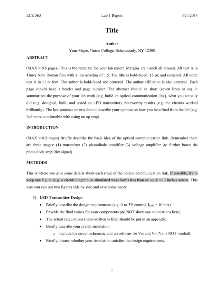
ECE 363 Lab 1 Report Fall 2014 Title Author Your Major, Union College, Schenectady, NY 12308 ABSTRACT (MAX = 0.5 pages) This is the template for your lab report. Margins are 1-inch all around. All text is in Times New Roman font with a line-spacing of 1.5. The title is bold-faced, 18 pt, and centered. All other text is in 11 pt font. The author is bold-faced and centered. The author affiliation is also centered. Each page should have a header and page number. The abstract should be short (seven lines or so). It summarizes the purpose of your lab work (e.g. build an optical communication link), what you actually did (e.g. designed, built, and tested an LED transmitter), noteworthy results (e.g. the circuits worked brilliantly). The last sentence or two should describe your opinion on how you benefited from the lab (e.g. feel more comfortable with using an op amp). INTRODUCTION (MAX = 0.5 pages) Briefly describe the basic idea of the optical communication link. Remember there are three stages: (1) transmitter (2) photodiode amplifier (3) voltage amplifier (to further boost the photodiode amplifier signal). METHODS This is where you give some details about each stage of the optical communication link. If possible, try to keep any figure (e.g. a circuit diagram or simulated waveform) less than or equal to 3 inches across. This way you can put two figures side by side and save some paper. 1) LED Transmitter Design Briefly describe the design requirements (e.g. 0-to-5V control, ILED = 10 mA). Provide the final values for your components (do NOT show any calculations here). The actual calculations (hand-written is fine) should be put in an appendix. Briefly describe your prelab simulation: o Include the circuit schematic and waveforms for VIN and Vo (VB is NOT needed). Briefly discuss whether your simulation satisfies the design requirements. 1 ECE 363 Lab 1 Report Fall 2014 2) Photodiode amplifier Include a schematic of the photodiode amplifier (OK to cut and paste from handout). Briefly explain how the op amp acts as a voltage-to-current converter. Briefly explain why a JFET-input op amp is a good choice for a photodiode amplifier. Briefly explain why the 1 nF capacitor is needed. 3) Voltage amplifier Include a schematic of the inverting amplifier (OK to cut and paste from handout). Briefly explain how an inverting amplifier works. Briefly explain why trimming is needed. EXPERIMENTS AND RESULTS This is where you describe your testing and measurements (e.g. scope snapshots). Your figures do not have to be in color – grayscale figures are OK. If possible, keep each figure to be less than or equal to 3 inches across. This way you can place two figures side by side and save some paper. You can simply state the “final answer” to requested calculations. Please attach calculations (hand-written is fine) in an appendix. Please be neat and clearly label the calculations (e.g. computing input bias current). For your convenience, the expected results are shown below (Buma is so kind ): 1) LED Transmitter o Scope snapshot of Vo (Vin and Vbase are NOT needed). o Based on the Vo scope trace, compute the LED current (transistor base current is not needed). o Comment on the level of agreement between your Vo scope trace and simulated waveform. 2) Photodiode amplifier o Scope snapshot of VPD. o Measured peak-to-peak voltage of VPD. o Compute the maximum and minimum photodiode current. o Comment on the photodiode sensitivity to the room lights. 3) Op amp properties o Measured V+ and V- o Computed input bias current and input offset current. o Measured Vo o Computed input offset voltage 2 ECE 363 Lab 1 Report Fall 2014 4) Voltage amplifier o Scope snapshot of 20 Hz LED signal. o Scope snapshot of TV remote (if you didn’t get a chance to do this, don’t worry about it). DISCUSSION This is where you discuss the agreement (or disagreement) between your circuit design and test measurements. Keep in mind that an error of a few percent is pretty much as good as you can get. If the error is more like 10% or 20% (or more), then you are expected to think about possible explanations and include them in the report. No figures are needed in this section. How successful was your LED transmitter design? The photodiode is clearly sensitive to the room lights. This can be problematic when detecting a TV remote control from across the room, where the desired signal may be considerably fainter than the room lights. How would you improve the design of the optical communication link to make it less sensitive to the room lights? Do not suggest operating the optical communication link with the room lights turned off (-300 points).This is your chance to exercise your engineering imagination and suggest some possible techniques! Overall, did your circuits work the way you expected? Any peculiarities? CONCLUSIONS This is where you write about the concepts or any valuable lessons you learned in the lab. If possible, discuss how they relate to other aspects of the course or to the general field of electronics. Your conclusion section should NOT be a summary of your results or what tasks you performed. The conclusion is supposed to reveal what you have learned from your lab experience. Make sure you refer to your simulated and measured results. Fall 2014 3

