FDM - SAITM Gurgaon
advertisement

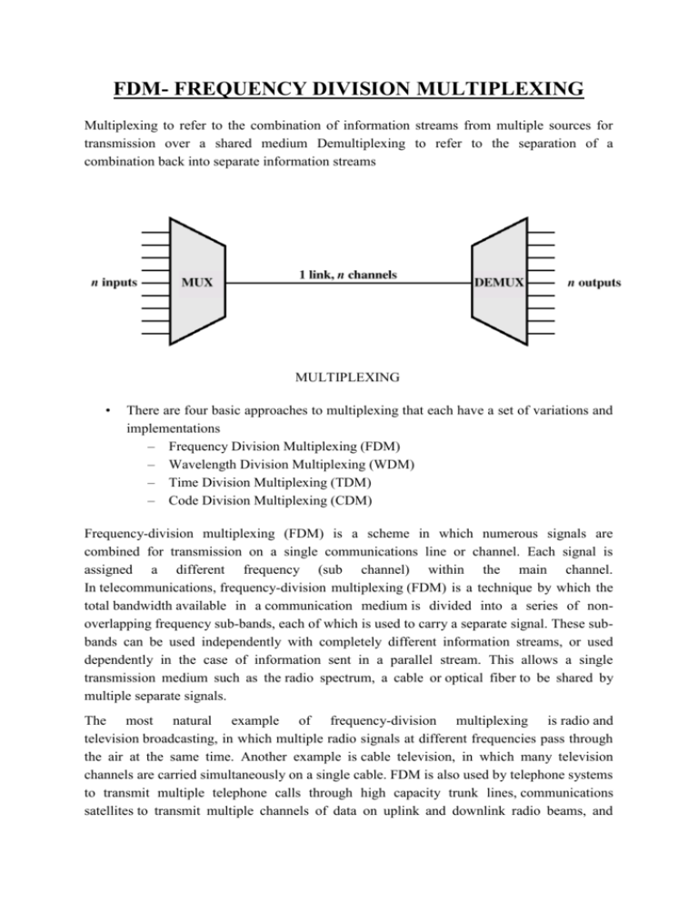
FDM- FREQUENCY DIVISION MULTIPLEXING Multiplexing to refer to the combination of information streams from multiple sources for transmission over a shared medium Demultiplexing to refer to the separation of a combination back into separate information streams MULTIPLEXING • There are four basic approaches to multiplexing that each have a set of variations and implementations – Frequency Division Multiplexing (FDM) – Wavelength Division Multiplexing (WDM) – Time Division Multiplexing (TDM) – Code Division Multiplexing (CDM) Frequency-division multiplexing (FDM) is a scheme in which numerous signals are combined for transmission on a single communications line or channel. Each signal is assigned a different frequency (sub channel) within the main channel. In telecommunications, frequency-division multiplexing (FDM) is a technique by which the total bandwidth available in a communication medium is divided into a series of nonoverlapping frequency sub-bands, each of which is used to carry a separate signal. These subbands can be used independently with completely different information streams, or used dependently in the case of information sent in a parallel stream. This allows a single transmission medium such as the radio spectrum, a cable or optical fiber to be shared by multiple separate signals. The most natural example of frequency-division multiplexing is radio and television broadcasting, in which multiple radio signals at different frequencies pass through the air at the same time. Another example is cable television, in which many television channels are carried simultaneously on a single cable. FDM is also used by telephone systems to transmit multiple telephone calls through high capacity trunk lines, communications satellites to transmit multiple channels of data on uplink and downlink radio beams, and broadband DSL modems to transmit large amounts of computer data through twisted pair telephone lines, among many other uses. An analogous technique called wavelength division multiplexing is used in fiber optic communication, in which multiple channels of data are transmitted over a single optical fiber using different wavelengths (frequencies) of light. • • • • • • FDM Useful bandwidth of medium exceeds required bandwidth of channel Each signal is modulated to a different carrier frequency Carrier frequencies separated so signals do not overlap (guard bands) e.g. broadcast radio Channel allocated even if no data FDM SYSTEM SQUARE LAW MODULATOR Amplitude Modulators Two basic amplitude modulation principles are discussed. They are square law modulation and switching modulation. Square law modulator When the output of a device is not directly proportional to input throughout the operation, the device is said to be non-linear. The Input-Output relation of a non-linear device can be expressed as V0 = a0 + a1Vin + a2Vin2 + a3 Vin3 + a 4Vin4 + When the input is very small, the higher power terms can be neglected. Hence the output is approximately given by V0 = a0 + a1Vin + a2Vin2 When the output is considered up to square of the in put, the device is called a square law device and the square law modulator is as shown in the figure AM DIODE DETECTOR Diode detector basics A number of methods can be used to demodulate AM, but the simplest is a diode detector. It operates by detecting the envelope of the incoming signal which it does by rectifying the signal. Current is allowed to flow through the diode in only one direction, giving either the positive or negative half of the envelope at the output. If the detector is to be used only for audio detection it does not matter which half of the envelope is used, either will work equally well. Only when the detector is also used to supply the automatic gain control (AGC) circuitry will the polarity of the diode matter. The AM detector or demodulator includes a capacitor at the output. Its purpose is to remove any radio frequency components of the signal at the output. The value is chosen so that it does not affect the audio base-band signal. There is also a leakage path to enable the capacitor to discharge, but this may be provided by the circuit into which the demodulator is connected. This type of detector or demodulator is called a linear envelope detector because the output is proportional to the input envelope. DC return required In order for a diode detector to generate the required DC voltage, a DC return must be available within the circuit. supplied. This can be achieved by placing an RF choke across the input to the detector diode. This appears like an open circuit to radio frequency signals, but acts as a DC return path for the audio and other signals appearing from the detector. Diode detector advantages & disadvantages The diode detector is widely sued, but it has several advantages and disadvantages: Diode detector advantages Simplicity: The diode detector is very simple and is easy to construct. The circuit six very straightforward, consisting of a very few components. Low cost: Requiring so few components, and the fact that he components are not specialised, this form of detector is very cheap. Accordingly it is widely used in AM domestic radios. Diode detector disadvantages Distortion: Although the diode detector is able to operate in a reasonably linear fashion over a reasonable range, outside this range high levels of distortion are introduced, and even within the more linear range, distortion levels are not particularly low. It is adequate for small low cost radios. Selective fading: These detectors are susceptible to the effects of selective fading experienced on short wave broadcast transmissions. Here the ionospheric propagation may be such that certain small bands of the signal are removed. Under normal circumstances signals received via the ionosphere reach the receiver via a number of different paths. The overall signal is a combination of the signals received via each path and as a result they will combine with each other, sometimes constructively to increase the overall signal level and sometimes destructively to reduce it. It is found that when the path lengths are considerably different this combination process can mean that small portions of the signal are reduced in strength. An AM signal consists of a carrier with two sidebands Insensitive: Semiconductor diodes have a certain turn-on voltage. Accordingly the voltage has to reach a certain level before the diode is able to operate reasonably efficiently. SQUARE LAW DIODE DETECTOR It utilizes the non-linear portion of the dynamic current-voltage characteristic of a diode. It differs from the linear diode detector is that in this case the applied input carrier voltage is of small magnitude and hence is restricted to the excessively non linear portion of the dynamic characteristic, whereas in linear diode detector, a large amplitude modulated carrier voltage is applied to the diode and most of the operation takes place over the linear region of the characteristic. The diode is biased positively to shift the zero-signal operating point to the small current non linear region of the dynamic current-voltage characteristic. The capacitor-resistor combination constitutes the load. To study the operation of this detector, we may consider first only the resistor R to constitute the load impedance. Then the dynamic current-voltage characteristic ofthe diode. Superposition of modulated carrier voltage on the dynamic characteristic is also illustrated. This results in the output current waveform. Since the operation takes place over the non linear region of the characteristic the current waveform has its lower half compressed. This average current consists of a steady or D C component I and a time varying component at the modulation frequency. The shunt capacitor C bypasses all the radio frequency components leaving only the average component to flow through the load resistor R producing the desired detected output.


