ME 581: Simulation of Mechanical
Systems
Inverse Kinematics of a 4-Degree of
Freedom Robotic Manipulator
Katie Briggs
Abstract
Increasing interest in robotic autonomous systems
has lead to a research emphasis of object
recognition, path planning and obstacle avoidance
for mobile robotic systems.
External sensing
methodologies can alert a robotic system of
obstacles, and suggest a global pose, or (X, Y, Z)
coordinate for a robotic end effector to move to in
order to complete a desired task. Consequently,
each robotic system must have derived inverse
kinematics and dynamics to allow the manipulator,
or mobile base to accurately follow a commanded
trajectory. This report focuses on deriving the
inverse kinematics of a 4-degree of freedom
robotic arm to arrive at a desired global pose, or
follow an end-tip trajectory.
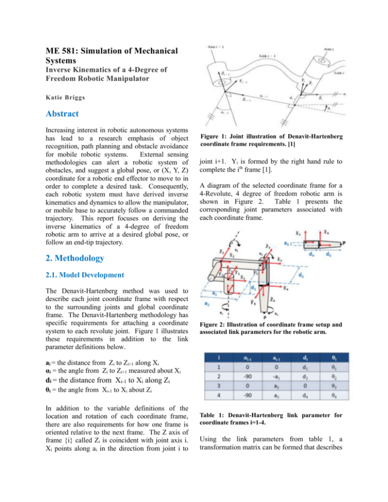
Figure 1: Joint illustration of Denavit-Hartenberg
coordinate frame requirements. [1]
joint i+1. Yi is formed by the right hand rule to
complete the ith frame [1].
A diagram of the selected coordinate frame for a
4-Revolute, 4 degree of freedom robotic arm is
shown in Figure 2.
Table 1 presents the
corresponding joint parameters associated with
each coordinate frame.
2. Methodology
2.1. Model Development
The Denavit-Hartenberg method was used to
describe each joint coordinate frame with respect
to the surrounding joints and global coordinate
frame. The Denavit-Hartenberg methodology has
specific requirements for attaching a coordinate
system to each revolute joint. Figure 1 illustrates
these requirements in addition to the link
parameter definitions below.
Figure 2: Illustration of coordinate frame setup and
associated link parameters for the robotic arm.
ai = the distance from Zi to Zi+1 along Xi
αi = the angle from Zi to Zi+1 measured about Xi
di = the distance from Xi-1 to Xi along Zi
θi = the angle from Xi-1 to Xi about Zi
In addition to the variable definitions of the
location and rotation of each coordinate frame,
there are also requirements for how one frame is
oriented relative to the next frame. The Z axis of
frame {i} called Zi is coincident with joint axis i.
Xi points along ai in the direction from joint i to
Table 1: Denavit-Hartenberg link parameter for
coordinate frames i=1-4.
Using the link parameters from table 1, a
transformation matrix can be formed that describes
the rotation and translation of coordinate frame i in
relation to coordinate frame i-1. Equation 1
derived the transformation T, from i to i-1 [1, 2].
(1.1)
sin i
0
ai 1
cos i
sin cos
cos
cos
sin
sin
i 1di
i
i 1
i
i 1
i 1
i 1
T
i
sin i sin i 1 cos i sin i 1 cos i 1 cos i 1di
0
0
0
1
(1.6)
1
0
4
5T
0
0
0 0 0
1 0 0
0 1 d5
0 0 1
A final description of the end point P with relation
to the global coordinate frame can be reached by
multiplying all transformation matrices together.
2.2. Forward Kinematics
(1.7)
Using the general transformation definition from
equation(1.1), transformation matrices for each
coordinate frame are created below, using
parameters from table 1.
(1.2)
cos 1
sin
1
0
1T
0
0
sin 1 0 0
cos 1 0 0
0
1 d1
0
0 1
(1.3)
cos 2
0
1
2T
sin 2
0
sin 2
0
cos 2
0
T T T T T T
0
5
1
2
2
3
3
4
4
5
Each index of the final matrix is represented by a
rotation, rii, or coordinate point Pi. This is used to
substitute for lengthy equations that belong to each
index of the final transformation matrix [1].
Equation (1.9) represents the global coordinates of
the arm end point P shown in Figure 2. Variables
PX, PY, and Pz correspond to the global X, Y, and
Z coordinates.
(1.8)
r11
r
0
21
T
5
r31
0
0 a1
1 d 2
0 0
0 1
0
1
r12
r22
r32
r13
r23
r33
0
0
PX
PY
PZ
1
(1.9)
(1.4)
cos 3
sin
3
2
3T
0
0
sin 3
cos 3
0
0
0 a2
0 0
1 0
0 1
PX c1[a1 a2c 2 a3 cos 23 s 23d5 d 4 s 23 ] d 2 s1
PY s1[a1 a2c 2 a3 cos 23 d 4 s 23 s 23d5 ] c1d 2
PZ d1 c 23d5 d 4c 23 a3 s 23 a2 s 2
(1.5)
cos 4
0
3
4T
sin 4
0
sin 4
0
cos 4
0
0 a3
1 d 4
0 0
0 1
Now that a forward kinematic description of the
robotic manipulator has been checked, it is useful
to verify the correctness of the math by isolating
each joint angle, and varying it from 0 to π to
validate the end point of the arm is at the correct
global coordinates. Figures 3, 4, and 5 below
confirm this validation process.
2.3. Inverse Kinematics and Matlab
Execution
Once the forward kinematics of the transformation
matrices has been validated, the inverse kinematic
equations can be derived. The inverse kinematics
of the robotic arm allows you to input a desired
trajectory and solve for the required joint angles,
velocities or joint accelerations to achieve
specified trajectory requirements for end point P.
Closed form solutions can be solved for joint
angles algebraically, however with increasing
complexity it is better to solve the equations
numerically, or with an iterative solving algorithm.
Figure 3: Yaw joint motion from 0 to π, shoulder
kept at 90 degrees, and elbow kept at zero degrees to
illustrate movement of arm.
Figure 4: Shoulder motion from 0 to π, elbow and
yaw joints kept at zero degrees.
When solving the inverse kinematics for a high
degree of freedom manipulator, there are often
many solutions to reach a specific coordinate.
Often times it is desired that the robotic arm keep
an “elbow up” configuration to prevent the arm
from hitting the ground or itself, like it would in
an elbow down configuration. Due to geometry
constraints, as well as joint limits, it is often
helpful to find a solution that is close to a specified
pose. For this reason, it is useful to use the
Newton-Raphson iterative technique to solve for
joint angles.
The Newton-Raphson equation works by
providing an initial guesstimate of all the model’s
states, such as estimated joint angles, and plugging
these states into the Newton-Raphson equation
below(1.10). The equation will get closer and
closer to a correct solution by minimizing the
system’s residuals, or error, to a given value
specified by the user.
qi 1 qi J 1 (qi ) T (qi )
(1.10)
The Jacobian and residuals used in (1.10) are
described in equations (1.11) , (1.12) and(1.13).
(1.11)
Figure 5: Elbow motion from 0 to π, shoulder joint
kept at 90 degrees, and yaw joint kept at zero
degrees.
PX X
T (qi ) PY Y
PZ Z
(1.12)
1
X
q 2 , T Y
3
Z
to follow. Figure 6 illustrates the general structure
of the Matlab code.
(1.13)
X
1
T Y
J (q) i
q j 1
Z
1
X X
2 3
Y Y
2 3
Z Z
2 3
The Jacobian matrix is derived by taking the
partial derivatives of PX, PY, and PZ from equation
(1.9) with respect to θ1, θ2, and θ3. The residual δT
is computed by plugging the guesstimate angles
into the forward kinematic equations (1.9) to solve
for PX, PY, and PZ. The residual is the difference
between the resulting P coordinate values, and the
desired X, Y, Z coordinate from the trajectory.
How big or small the residual is determines the
error between the robotic arm end point P, and the
desired trajectory coordinate. Once the NewtonRaphson equations have converged to a minimal
residual, the Jacobian matrix can be used to solve
for the joint velocities required achieve specified
end tip velocity. The equation to solve for joint
velocities is shown below [1, 2].
(1.14)
1
X
1
2 J Y
Z
3
The inverse kinematic equations (1.10)-(1.14)
above were put into a Matlab script to compute the
joint angles and velocities of the robotic arm as its
end point P moved along a specified trajectory.
Two loops were created within the Matlab script
containing an inner while loop and outer for loop.
The inner while loop used the Newton-Raphson
equations to solve for joint angles and joint
velocities until the residual reached a specified
tolerance. The outer for loop iterated along a
desired trajectory, specifying a new X, Y, Z end tip
coordinate and corresponding velocity for the arm
Figure 6: Outline of Matlab script
3. Simulation and Results
A simple straight line trajectory was simulated
with the following values from i=1:101:
(1.15)
i
0.5
PX
100 [m]
P d d [m]
5
Y 4
[m]
PZ
a2
X 0.1 [m/s]
Y 0 [m/s]
Z 0 [m/s]
1
Global Z [m]
0.8
0.6
0.4
0.2
0
0.6
0.4
0.4
0.2
0.2
0
0
Global Y [m]
-0.2
-0.2
-0.4
Theta 1 [rad]
Theta 2 [rad]
Theta 3 [rad]
-1.8
-1.9
-2
20
0
20
0
20
-0.15
-0.2
0
20
40
60
80
100
Point along trajectory path
Plot of Shoulder Joint Along Trajectory
0
20
0
20
0.1
0
-0.1
40
60
80
100
Point along trajectory path
Plot of Elbow Joint Along Trajectory
120
0.1
0
-0.1
40
60
80
Point along trajectory path
100
120
4. Conclusion
40
60
80
100
Point along trajectory path
Plot of Shoulder Joint Along Trajectory
40
60
80
100
Point along trajectory path
Plot of Elbow Joint Along Trajectory
120
120
0.8
0.7
40
60
80
Point along trajectory path
120
Figure 9: Plots of joint velocities along the trajectory
Plot of Yaw Joint Along Trajectory
0
Plot of Yaw Joint Along Trajectory
-0.1
Global X [m]
Figure 7: Arm link outline as it follows the
trajectory
2
1.5
1
Theta1 dot [rad/sec]
Arm motion along trajectory
Theta3 dot [rad/sec] Theta2 dot [rad/sec]
Using these trajectory values, corresponding joint
angles and joint velocities were solved for within
Matlab. Plots of the resulting joint angles and
velocities are shown below.
100
120
Figure 8: Plot of joint angles along trajectory path
Computation of joint angles and joint
velocities using the Newton-Raphson iterative
method has many useful applications within
the field of robotics. Robotic manipulators are
often used to assist and perform dexterous
tasks that require the arm end effector to
follow a trajectory at a given speed. These
tasks are possible through inverse kinematics
and dynamics. This paper has provided an
initial overview of the steps taken to analyze
the inverse kinematics of a 3-dimensional
mechanism to assess joint speeds while
conducting a commanded task.
References
[1] Craig, J., Introduction to Robotics
Mechanics and Control, Third edition,
Chapter 3, Manipulator Kinematics,
Pearson Prentice Hall, New Jersey, USA,
2005.
[2] R. Jazar.: Theory of Applied Robotics,
Second edition, Springer, New York,
USA, 2010.


