DOCX - Cern
advertisement
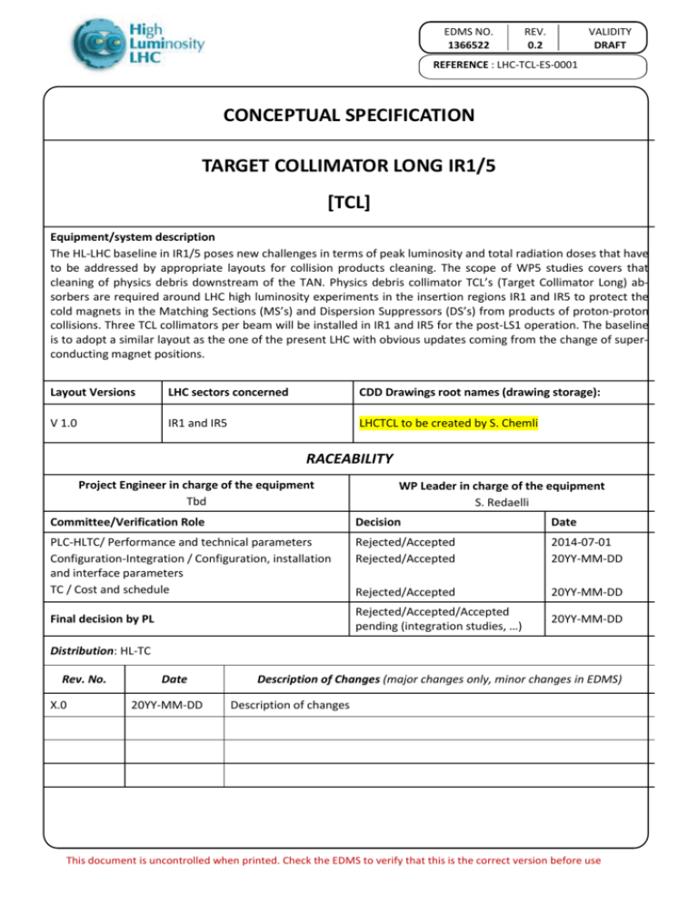
EDMS NO. 1366522 REV. 0.2 VALIDITY DRAFT REFERENCE : LHC-TCL-ES-0001 CONCEPTUAL SPECIFICATION TARGET COLLIMATOR LONG IR1/5 [TCL] Equipment/system description The HL-LHC baseline in IR1/5 poses new challenges in terms of peak luminosity and total radiation doses that have to be addressed by appropriate layouts for collision products cleaning. The scope of WP5 studies covers that cleaning of physics debris downstream of the TAN. Physics debris collimator TCL’s (Target Collimator Long) absorbers are required around LHC high luminosity experiments in the insertion regions IR1 and IR5 to protect the cold magnets in the Matching Sections (MS’s) and Dispersion Suppressors (DS’s) from products of proton-proton collisions. Three TCL collimators per beam will be installed in IR1 and IR5 for the post-LS1 operation. The baseline is to adopt a similar layout as the one of the present LHC with obvious updates coming from the change of superconducting magnet positions. Layout Versions LHC sectors concerned CDD Drawings root names (drawing storage): V 1.0 IR1 and IR5 LHCTCL to be created by S. Chemli RACEABILITY Project Engineer in charge of the equipment Tbd WP Leader in charge of the equipment S. Redaelli Committee/Verification Role Decision Date PLC-HLTC/ Performance and technical parameters Configuration-Integration / Configuration, installation and interface parameters TC / Cost and schedule Rejected/Accepted Rejected/Accepted 2014-07-01 20YY-MM-DD Rejected/Accepted 20YY-MM-DD Rejected/Accepted/Accepted pending (integration studies, …) 20YY-MM-DD Final decision by PL Distribution: HL-TC Rev. No. X.0 Date 20YY-MM-DD Description of Changes (major changes only, minor changes in EDMS) Description of changes This document is uncontrolled when printed. Check the EDMS to verify that this is the correct version before use EDMS NO. 1366522 REV. 0.2 VALIDITY DRAFT REFERENCE : LHC-TCL-ES-0001 1 CONCEPTUAL DESCRIPTION 1.1 Scope At the nominal LHC performance, with design luminosity of 1034cm-1s-2 at 7 TeV, the products of collision might quench the superconducting magnets in the MS’s downstream of the collision points. Three TCL collimators per beam per IP (interaction point) side will be available for the post-LS1 (long shutdown 1) operation in IR1 and IR5 to mitigate this problem: during LS1 two new TCL collimators made of Cu and W heavy alloy were installed in front of the Q4 and Q6 magnets, complementing the Run 1 layout that had only one TCL in front of the Q5. The new proposed layout ensures maximum flexibility for the operation of the forward-physics detectors and can also provide a significant reduction of the losses in the DS’s further downstream [1]. The high luminosity upgrade of the LHC foresees peak luminosities during proton operation up to 7.5x1034cm-1s-2 [2], thus posing further challenges for physics debris collimation. The initial HL-LHC layout baseline foresees a similar layout to the one deployed for the LHC, including three TCL collimators per beam per IR, with additional fixed masks described in [3]. 1.2 Benefit or objective for the HL-LHC machine performance The TCL collimators in IR1/5 are needed to keep matching section magnets and dispersion suppressor magnets safely below the quench limits during high-luminosity proton operation and to limit the total integrated doses in the magnets [4]. The TCL might also be used to optimize the distribution of radiation around the interaction regions. Without these collimators, the HL-LHC performance will be reduced in terms of peak and integrated luminosity. The addition of TCL collimators also in IR8 is under discussion but not presently in the baseline. 1.3 Equipment performance objectives The new physics debris collimators must: Ensure that the MS and DS magnets are below quench limits with peak luminosities up to 7.5x1034cm-1s-2; Keep total doses on MS and DS magnets below their radiation damage limits, with appropriate margins, for the design HL integrated luminosity goal of 3000 fb-1; Ensure efficient operation in high-radiation environments, to allow the 3000 fb-1 HL goal. Page 2 of 6 Template EDMS No.: 1311290 EDMS NO. 1366522 REV. 0.2 VALIDITY DRAFT REFERENCE : LHC-TCL-ES-0001 TECHNICAL ANNEXES 2 PRELIMINARY TECHNICAL PARAMETERS 2.1 Assumptions Key machine parameters that affect the TCL layout requirements are the (1) peak luminosity at the beginning of the fill (7.5x1034cm-1s-2); (2) total integrated luminosity (3000 fb-1). It is noted that the settings of the TCL collimators will have to be chosen carefully taking into account collimator hierarchy and machine impedance constraints. The design goal is that their contribution to the total machine impedance should be negligible. 2.2 Equipment Technical parameters Table 1: Equipment parameters Characteristics Jaw active length Jaw material Flange-to-flange distance Number of jaws Orientation Number of motors per jaw Number of BPMs per jaw RF damping Cooling of the jaw Cooling of the vacuum tank Minimum gap Maximum gap Stroke across zero Angular adjustment Jaw coating Transverse jaw movement (5th axis) Units Value mm -mm -------mm mm mm ---- 1000 W heavy alloy (TBD) 1480 (to be reviewed) 2 Horizontal 2 2 Fingers Yes Yes <1 > 60 (to be reviewed) >5 Yes No Yes The parameters above are based on the present TCL/TCT collimator design. Note that possible improvements of the TCL designs are being considered (see also 3.1 and 3.2): - Thicker jaws for better magnet protection; - Shorter flange-to-flange length for better integration in the D2/TAN regions; - Maximum stroke to accommodate larger beta functions. At this stage, we consider to build new collimators that feature also jaw-integrated BPM’s for a better setting control and for a faster collimator setup, improving the TCL baseline adopted for the LHC. 2.3 Operational parameters and conditions The TCL collimators are for the moment planned to be used during proton operation only. They will be moved to settings of 10-20 local beam sizes before – or while – bringing the beams in collision, to ensure that they are in place at the beginning of physics production (magnet protected when the peak luminosity is reached). The TCL’s can remain at parking positions in the other operational phases. Page 3 of 6 Template EDMS No.: 1311290 EDMS NO. 1366522 REV. 0.2 VALIDITY DRAFT REFERENCE : LHC-TCL-ES-0001 The TCL’s are designed to have a negligible contribution to the total machine impedance. The proposed locations for TCL installation are expected not to be effective in removing the most critical debris losses during ion operation (ion beams from bound-free pair production mechanisms at collision can only be intercepted at locations with higher dispersion [5]). The TCL collimator might be used also during ion operation if proved useful. Present operational scenarios do not consider compatibility with forward-physics programs, at least in the HL baseline. 2.4 Technical and Installation services required For the ultimate HL implementation, new collimator slots with complete services must be foreseen, following the change of magnet positions. The cabling of the already installed TCL collimators might be re-used. Note that the present TCL design does not include embedded BPMs. Additional cabling is therefore required for this functionality. Table 2: Technical services Domain Electricity & Power Cooling & Ventilation Cryogenics Control and alarms Vacuum Instrumentation Requirement YES Active cooling for the jaws (demineralized water) -YES YES. The vacuum team recommends the use of Conflat gaskets. YES Table 3: Installation services Domain Civil Engineering Handling Alignment 2.5 Requirement NO YES – special transport YES P & I Diagrams -- 2.6 Reliability, availability, maintainability Same standards as the other collimators. 2.7 Radiation resistance All collimator components are optimized for operation in high radiation environments. This is an important constraint for the collimators in the experimental regions. Total doses on the TCL’s will be dominated by the radiation environment due to high-luminosity interactions. The selection of construction materials will take activation properties into account. The design is optimized to allow for fast repair, maintenance and replacement, depending on expected residual dose rate levels. The design also considers dismantling, radioactive waste conditioning and disposal properties at the end of the lifetime of the component. Page 4 of 6 Template EDMS No.: 1311290 EDMS NO. 1366522 REV. 0.2 VALIDITY DRAFT REFERENCE : LHC-TCL-ES-0001 2.8 List of units to be installed and spares policy The total number of new devices is 12 (3 per beam per IR1/5). Note that present spare collimators in W might be reused (if available with the embedded BPM design). An appropriate spare policy will be established when the total number of installed units will be known. Indicatively, we assumed 10-20 % of the installed units. Possible installation of 1 TCL per beam in IR8 is also under investigation. 3 PRELIMINARY CONFIGURATION AND INSTALLATION CONSTRAINTS 3.1 Longitudinal range The longitudinal position of the baseline presently under study are given in [5]: one TCL on the IPside of D2, Q5 and Q6 is foreseen. Ideally, the shortest distance between the TCL jaws and the superconducting coils must be foreseen, depending on the detailed layouts of warm/cold transitions. 3.2 Volume Standard collimator design, as the presently installed collimators, should be assumed. It is important to recall that the collimator integration in the region between TAN and D2 magnets (present location where two tertiary collimators and one TCL are located) must be studies properly, taking into account the constraints coming from the reduced separation between the two beam pipes. Additional space must be provisioned for fixed masks [3]. It is also noted that the collimator jaw stroke might need to be updated compared to the present design (see also Table 1) depending on the final * values decided for HL-LHC. More advanced collimator design, foreseeing for example a thicker jaw to improve magnet protection, are under investigation. 3.3 Installation/Dismantling Dismantling and possible re-location of the present TCL’s infrastructure. The new slots required follow the updated magnet layout positions. 4 PRELIMINARY INTERFACE PARAMETERS 4.1 Interfaces with equipment Standard as present collimators. 4.2 Electrical interfaces No changes for any magnet powering system. 5 COST & SCHEDULE 5.1 Cost evaluation Cost to be charged on the collimation code 61064. 5.2 Approximated Schedule At present, the TCL design baseline relies on standard collimator design with integrated BPM’s. Therefore, here we foresee simply a production line starting in adequate time for produc- Page 5 of 6 Template EDMS No.: 1311290 EDMS NO. 1366522 REV. 0.2 VALIDITY DRAFT REFERENCE : LHC-TCL-ES-0001 tion/installation of 12 units plus spares by the end of LS3. Note that presently available collimator spares might be used as TCL’s. Should the need for new designs/advanced material be demonstrated, the schedule shall be updated accordingly, e.g. by foreseeing adequate prototyping and validation phases prior to production. Table 4: Tentative schedule Phase 2014 2015 2016 2017 2018 2019 2020 2021 2022 Funct. Spec. prototype Production batch 1 5.3 Schedule and cost dependencies None. 6 TECHNICAL REFERENCE DOCUMENTS [1] 168th meeting of the LHc Collimation Working Group, https://indico.cern.ch/event/294798/ [2] HL-LHC Parameter & Layout Committee page, https://espace.cern.ch/HiLumi/PLC/default.aspx [3] HL Conceptual Functional Specification, TCLM, https://edms.cern.ch/document/1393868 [4] L. Esposito et al., “Energy deposition including matching section with latest layout version”, presentation at the 3rd HiLumi Annual meeting, Daresbury, UK (2013), https://indico.cern.ch/event/257368/ [5] HiLumi WP5 deliverable document D5.3, https://cds.cern.ch/record/1557081/files/CERN-ACC2013-008.pdf 7 APPROVAL PROCESS COMMENTS FOR VERSION X.0 OF THE CONCEPTUAL SPECIFICATION 7.1 PLC-HLTC / Performance and technical parameters Verification Comments or references to approval notes. In case of rejection detailed reasoning 7.2 Configuration-Integration / Configuration, installation and interface parameters Verification Comments or references to approval notes. In case of rejection detailed reasoning 7.3 TC / Cost and schedule Verification Comments or references to approval notes. In case of rejection detailed reasoning 7.4 Final decision by PL Comments or references to approval notes. In case of rejection detailed reasoning Page 6 of 6 Template EDMS No.: 1311290
