ParaxialOpticsReview
advertisement
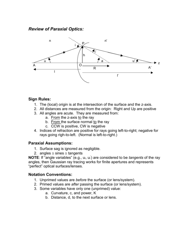
Review of Paraxial Optics: n n’ P i i’ h u u’ a O A z A’ R l l’ Sign Rules: 1. The (local) origin is at the intersection of the surface and the z-axis. 2. All distances are measured from the origin: Right and Up are positive 3. All angles are acute. They are measured from: a. From the z-axis to the ray b. From the surface normal to the ray c. CCW is positive, CW is negative 4. Indices of refraction are positive for rays going left-to-right; negative for rays going righ-to-left. (Normal is left-to-right.) Paraxial Assumptions: 1. Surface sag is ignored as negligible. 2. angles sines tangents NOTE: If “angle variables” (e.g., ui, ui’) are considered to be tangents of the ray angles, then Gaussian ray tracing works for finite apertures and represents “perfect” optical surfaces/lenses. Notation Conventions: 1. Unprimed values are before the surface (or lens/system). 2. Primed values are after passing the surface (or lens/system). 3. Some variables have only one (unprimed) value: a. Curvature, c, and power, K b. Distance, d, to the next surface or lens. Ray Tracing Equations: Refract at a surface nu nu hK Refract through a thin lens in air u u hK hi 1 hi diui Transfer Imaging Equations: n n K l l 1 1 K l l li 1 li di Image location from a surface Image location from a thin lens in air Image transfer Lenses: K cn n K n 1c1 c2 Power of a surface Power of a thin lens in air. (n = the index of the lens material) (𝑛−1)2 𝐾 ≡ (𝑛 − 1)(𝑐1 − 𝑐2 ) + 𝑐1 𝑐2 𝑑 𝑛 Power of a thick lens (thickness = d) 𝐾 = 𝐾1 + 𝐾2 − 𝐾1 𝐾2 𝑑 Power of two thin lenses in air separated by d. ℎ 𝐾 = 𝐾1 + 2 𝐾2 + ⋯ Power of two (or more) thin lenses based on a parallel ray ℎ1 trace. 1 f K 1 c R Focal length curvature is inverse radius of surface Magnification: n n’ l’ O i i’ O’ l For a thin lens in air (n = n’ = 1), the magnification is simply the ratio of the image size to the object size: 𝑂′ 𝑙 ′ 𝑀= = 𝑂 𝑙 The second relation follows from similar triangles, and if we are talking about a compound system, the distances are measured from the principle planes. (Note that the object heights will always have the correct sign, even in a compound system, but that the ratio of image to object distances won’t, unless all the intermediate magnifications are taken into account:) 𝑀 = 𝑛𝑙′ 𝑙′ 𝑙 ∙ 𝑙′′ 𝑙′ ∙ 𝑙′′′ 𝑙′′ ∙⋯ If n’≠ n, then n i = n’i’, and then 𝑀 = 𝑛′ 𝑙 Graphical Ray Tracing Derived from paraxial formulas: Ray parallel to axis: u u hK hK , since u 0 h h 1 u l f l u K Hence the ray passes through the focal point. Ray passing through focal point: h h h u u hK hK 0 , since u f l f Hence the ray leaves the lens parallel to the axis. Ray passing through lens vertex: u u hK u , since h 0 Hence the ray is undeviated. Summary of Graphical Rays: I) Incident rays parallel to the axis, pass through the focal point. (The corollary is that incident rays that pass through the focal point emerge parallel to the axis.) II) Rays through the center of the lens are undeviated. In the paraxial approximation, the lens is an infinitesimally thin planeparallel plate at the center. III) Any parallel bundle of rays will meet at the focal plane at the point where the central (undeviated) ray in the bundle meets that plane. The “focal plane” is a plane perpendicular to the axis at the focal distance. The central ray of a bundle is often called the “chief ray”. Examples of Graphical Ray Tracing: a) Real object Real image F F’ F F’ (additional ray) Virtual image at ∞ b) Real object c) (additional ray) (additional ray) Real image at ∞ Virtual image F Real object F’ d) Virtual object F Real F’ image (additional ray) Stops and Pupils of an optical system: Marginal Ray Chief Ray The marginal ray is drawn from the axis at the object position and passes through the edge of the aperture stop. The chief ray is drawn from the edge of the object (or object field of view) through the center of the aperture stop. The system APERTURE STOP is the aperture that limits the marginal ray angle from a field point. The Entrance Pupil is the image of the aperture stop seen from object space. The Exit Pupil is the image of the stop seen from image space. Any ray coming from object space that is aimed at the center of the entrance pupil will pass through the center of the aperture stop and (appear to come from) the center of the exit pupil, as seen from image space. The stop can be found by drawing a marginal ray (solid line) through the system. The limiting aperture stop is the aperture that the ray is closest to the edge of, in a proportional sense. (Here the aperture stop is Lens 2) L3 L1 L2 Everywhere the marginal ray (solid line) crosses the axis is an image position. The height of the chief ray (dotted line) at those positions gives the size of the image. Geometric DOF: Ignoring diffraction, the Depth of Field (DOF) and depth of focus (dof) are strictly a function of the geometry of the optical system and the pixel size (or, alternatively, the “acceptable blur diameter”) of the detector. The following illustrates the determination of the geometric dof and DOF: DOF dof u u’ b B The drawing is not to scale – both the DOF and dof would be much smaller than shown in a practical system. Given the approximation that the magnification and conjugate relationship are approximately constant over the DOF and dof (that is, the DOF is imaged onto the dof), we have (assuming absolute values of all quantities): B b b u , u , M DOF dof B u b B 1 b dof hence : DOF M 2 2 u M u M u M u Also, in the approximation where sin tan, we have: b b dof 2b FNO u NA Hyperfocal Distance: The hyperfocal distance is defined as the distance to focus a camera such that objects at infinity will still be “acceptably” in focus (i.e., the PSF will not be larger than the acceptable blur diameter). The following drawing illustrates an optical system focused at the hyperfocal distance: l’ dZ b F Objects at focus at F, with the maximum blur diameter, b. The lens is focused at the conjugate of l’ = F+dZ/2, and the minimum in focus distance is the conjugate of l’+dZ. Hence, the hyperfocal distance (point of focus) is: 1 1 1 l F F z 2 2F 2 F2 l F F z b f # and the near conjugate is: 1 1 1 F z l F F2 F2 l F F z 2b f # where f# is the focal length divided by the aperture. (Note that Wikipedia gets this formula wrong.) Using Gaussian ray traces to generate lens formulas: Trace a horizontal, marginal ray through two lenses (why a horizontal ray?): n1 n1’=n2 n2’ u1=0 h1 u1’=u2 u2’ h2 f d1 K1 K2 Note that: u2’ = -h1/f (definition of f for the combination) Refract through first element: n1u1 n1u1 h1 K1 u1 h1 K1 , since u1 0 n1 h1 K1 , u 2 u1 , n2 n1 n2 Transfer to second element: h2 h1 u1d1 u2 h1 K1 d1 n2 Refract at second element: n2 u 2 n2 u 2 h2 K 2 h2 h1 hK hK n2 1 1 h1 1 1 d1 K 2 n2 n2 h KK n2 1 h1 K1 h1 K 2 h1 1 2 d1 n2 f 1 Eliminating h1 and using K where K is the combination power, we get the: f General formula for combination of two systems. n2 K K1 K 2 K1 K 2 d1 n2 (Easy to remember & independent of the sign convention) Why doesn’t n1 enter into this equation? (n1 is included in the calculation of K1) Thick Lens Equation: n2 1, n n2 , d d1 Let: K1 c1 n 1 (power of 1st surface) K 2 c2 1 n (power of 2nd surface) K c1 n 1 c2 1 n c1c2 n 11 n d Then: n 1 d n 1c1 c2 c1c2 n Or, in terms of focal length and radii: 1 1 1 n 1 n 1 d f R R nR R 2 1 2 1 n Thick lens formula (Lensmaker’s formula) Thin Lens Equation: Just set d=0 in the thick lens equation: 1 1 1 n 1 f R1 R2 Focal length of lenses not in air: Suppose that n2’ 1 (lens is not in air): Then, the LHS of the lens equations becomes n 2 , and K2 will be calculated f differently. Two thin lenses spaced in air: n2 n2 1 Let: K1 Then: 1 1 , K2 f1 f2 1 1 1 d f f 1 f 2 f1 f 2 (This also works for thick lenses, if d is measured between principle planes) Afocal systems: Suppose that K1K 2 d K1 K 2 K 0, f 1 1 Then K1 K 2 f1 f2 d f1 f 2 1 K1 K 2 f1 f 2 Hence if the lenses are spaced by the sum of their focal lengths, we get an afocal system – e.g., a telescope. Zoom lens: What happens if d = f1 ? Then f = f1 and the second lens has no effect on the total power at all. This is the principle behind zoom lenses: The power contribution of a lens (or lens group) to the total lens is dependent on the relative positions of the lenses.
