molar adiabatic
advertisement
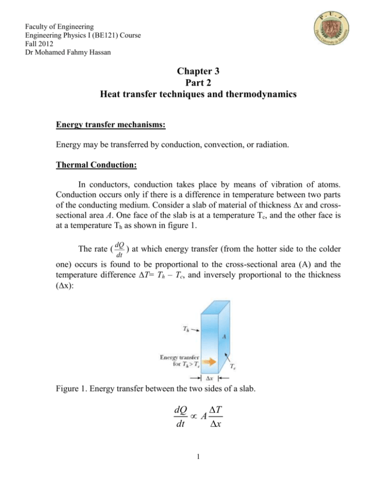
Faculty of Engineering Engineering Physics I (BE121) Course Fall 2012 Dr Mohamed Fahmy Hassan Chapter 3 Part 2 Heat transfer techniques and thermodynamics Energy transfer mechanisms: Energy may be transferred by conduction, convection, or radiation. Thermal Conduction: In conductors, conduction takes place by means of vibration of atoms. Conduction occurs only if there is a difference in temperature between two parts of the conducting medium. Consider a slab of material of thickness x and crosssectional area A. One face of the slab is at a temperature Tc, and the other face is at a temperature Th as shown in figure 1. The rate ( dQ ) at which energy transfer (from the hotter side to the colder dt one) occurs is found to be proportional to the cross-sectional area (A) and the temperature difference T= Th – Tc, and inversely proportional to the thickness (x): Figure 1. Energy transfer between the two sides of a slab. dQ T A dt x 1 Faculty of Engineering Engineering Physics I (BE121) Course Fall 2012 Dr Mohamed Fahmy Hassan dQ T kA dt x Where the proportionality constant k is the thermal conductivity of the material. Substances that are good thermal conductors have large thermal conductivity values, whereas good thermal insulators have low thermal conductivity values. If the slab is of infinitesimal thickness, then: dQ dT kA dt dx Suppose that a long, uniform rod of length L is thermally insulated so that energy cannot escape by heat from its surface except at the ends, as shown in figure 2. One end is in thermal contact with an energy reservoir at temperature Tc , and the other end is in thermal contact with a reservoir at temperature Th>Tc . When a steady state has been reached, the temperature at each point along the rod is constant, so: dT Th Tc dx L dQ T Tc kA h dt L Figure 2. Energy transfer between the two sides of an insulated rod. For a compound slab containing several materials of thicknesses L1, L2,... and thermal conductivities k1, k2,…, as shown in figure 3, the rate of energy transfer through the slab at steady state is: ATh Tc dQ Li dt i ki 2 Faculty of Engineering Engineering Physics I (BE121) Course Fall 2012 Dr Mohamed Fahmy Hassan where Tc and Th are the temperatures of the outer surfaces (which are held constant) and the summation is over all slabs. Figure 3. Energy transfer by conduction through compound slab containing several materials in thermal contact with each other. At steady state, the rate of energy transfer through all slabs is the same. Example: Two slabs of area=1m2 and thicknesses, L1=10 cm and L2=5 cm, and thermal conductivities k1 =397 W/m C, and k2 =238 W/m C are in thermal contact with each other, as shown in figure. In the steady-state condition, the temperatures of their outer surfaces are Tc=20C and Th=50C, respectively. Determine the rate of energy transfer by conduction through the slabs and the temperature at the interface in the steady-state condition. Solution The rate of energy transfer by conduction through the slabs is: 3 Faculty of Engineering Engineering Physics I (BE121) Course Fall 2012 Dr Mohamed Fahmy Hassan dQ AT T L dt k h c i i i dQ AT T L L dt k k h c 1 1 1 1 dQ 1 50 20 64.93 10 W 0.1 0.05 dt 397 238 3 To get the temperature at the interface in the steady-state condition: Notice the phrase “in the steady-state condition.” means that energy transfers through the compound slab at the same rate at all points. The rate at which energy is transferred through slab 1= the rate at which energy is transferred through slab 2: 𝑘1 𝐴 ( 𝑇−𝑇𝑐 𝐿1 ) = 𝑘2 𝐴 ( 𝑇ℎ −𝑇 𝐿2 ) = 64.93 ×10³ For slab 2 𝑑𝑄 𝑇ℎ − 𝑇 = 𝑘2 × 𝐴 × ( ) 𝑑𝑡 𝐿2 50 T 64.93 10 3 238 1 0.05 T 36.4 C 4 Faculty of Engineering Engineering Physics I (BE121) Course Fall 2012 Dr Mohamed Fahmy Hassan Example Two rods of the same length (20×10-2 m) and same Area (5×10⁻² m2), but they are formed from different materials. They can be connected in series as in Figure (a). Th= 90oC and Tc= 30oC. When the energy transfer reaches steady state, calculate; (a) The rate of energy transfer by conduction when connected in series. (b) The temperature at the junction. (c) The total rate of energy transfer by conduction when connected in parallel as in fig (b). The thermal conductivity of rods 1 and 2 are 400 Wm-1K-1,and 200 Wm-1K-1 Solution The rate of energy transfer by conduction when connected in series 𝑑𝑄 𝐴 × 𝛥𝑇 = 𝐿 𝑑𝑡 ∑𝑖 𝑖 𝐾𝑖 5 × 10⁻² (90 − 30) = = 2000𝑊 20 × 10−2 20 × 10−2 + ( 400 200 ) The temperature at the junction 400 × 5 × 10−2 (90 − 𝑇) 2000 = = 70 𝑜𝐶 − 20 × 10 5 Faculty of Engineering Engineering Physics I (BE121) Course Fall 2012 Dr Mohamed Fahmy Hassan The total rate of energy transfer by conduction when connected in parallel; For rod 1 𝑑𝑄 𝐾 × 𝐴 × 𝛥𝑇 400 × 5 × 10−2 × 60 = = = 6000𝑊 𝑑𝑡 𝐿 20 × 10−2 For rod 2 𝑑𝑄 𝐾 × 𝐴 × 𝛥𝑇 200 × 5 × 10−2 × 60 = = = 3000𝑊 𝑑𝑡 𝐿 20 × 10−2 Then 𝑡𝑜𝑡𝑎𝑙 𝑑𝑄/𝑑𝑡 = 6000 + 3000 = 9000𝑊 Table of Thermal Conductivities Convection: At one time or another, you probably have warmed your hands by holding them over an open flame. In this situation, the air directly above the flame is heated and expands. As a result, the density of this air decreases and the air rises. This hot air warms your hands as it flows by. 6 Faculty of Engineering Engineering Physics I (BE121) Course Fall 2012 Dr Mohamed Fahmy Hassan Energy transferred by the movement of a warm substance is said to have been transferred by convection. If it were not for convection currents, it would be very difficult to boil water. As water is heated in a tea kettle, the lower layers are warmed first. This water expands and rises to the top because its density is lowered. At the same time, the denser, cool water at the surface sinks to the bottom of the kettle and is heated. The same process occurs when a room is heated by a radiator. The hot radiator warms the air in the lower regions of the room. The warm air expands and rises to the ceiling because of its lower density. The denser, cooler air from above sinks, and is wormed. Radiation: The third means of energy transfer is radiation. All objects radiate energy continuously in the form of electromagnetic waves produced by thermal vibrations of the molecules. The rate at which an object radiates energy is proportional to the fourth power of its absolute temperature. This is known as Stefan’s law and is expressed in equation form as: dQ AeT 4 dt Where dQ is the power in watts radiated from the surface of the object, is a dt constant equal to 5.6696 10-8 W/m2 K4, A is the surface area of the object in square meters, e is the emissivity, and T is the surface temperature in kelvins. The value of e can vary between zero and unity, depending on the properties of the surface of the object. Object radiates energy at a rate given by dQ AeT 4 , it also absorbs dt electromagnetic radiation. If the latter process did not occur, an object would eventually radiate all its energy, and its temperature would reach absolute zero. The energy an object absorbs comes from its surroundings, which consist of other objects that radiate energy. If an object is at a temperature T and its surroundings are at an average temperature T0, then the net rate of energy gained or lost by the object as a result of radiation is: 7 Faculty of Engineering Engineering Physics I (BE121) Course Fall 2012 Dr Mohamed Fahmy Hassan dQ Ae T 4 To4 dt When an object is in equilibrium with its surroundings, it radiates and absorbs energy at the same rate, and its temperature remains constant. When an object is hotter than its surroundings, it radiates more energy than it absorbs, and its temperature decreases. An ideal absorber is defined as an object that absorbs all the energy incident on it, and for such an object, e =1. An object for which e =1 is often referred to as a black body. An ideal absorber is also an ideal radiator of energy. In contrast, an object for which e = 0 absorbs none of the energy incident on it. Such an object reflects all the incident energy, and thus is an ideal reflector. Example: If the skin temperature of someone is 35°C, what is the net energy loss from his body in 10 min by radiation? The surroundings are at 20°C. Assume that the emissivity of skin is 0.9, the surface area of him is 1.50 m2 and = 5.6696 10-8 W/m2 K4. Solution dQ Ae T 4 To4 dt dQ 4 4 5.6696 10 8 1.5 0.9 35 273 20 273 dt dQ 125 W dt The total energy lost in 10 min is: dQ Q t 125 600 75 10 3 J dt 8 Faculty of Engineering Engineering Physics I (BE121) Course Fall 2012 Dr Mohamed Fahmy Hassan Ideal Gas Law The equation of state for an ideal gas is, PV = n R T This is known as the ideal gas law R is a constant, called the Universal Gas Constant R = 8.314 J/ mol K From this, you can determine that 1 mole of any gas at atmospheric pressure and at 0o C is 22.4 L The internal energy of Monatomic Gas For a monatomic gas, translational kinetic energy is the only type of energy the particles of the gas can have Therefore, the total energy is the internal energy: Eint 3 n RT 2 Thermodynamics State Variables State variables describe the state of a system In the macroscopic approach to thermodynamics, variables are used to describe the state of the system Pressure, temperature, volume, internal energy These are examples of state variables The macroscopic state of an isolated system can be specified only if the system is in internal thermal equilibrium Transfer Variables Transfer variables have values only when a process occurs in which energy is transferred across the boundary of a system Transfer variables are not associated with any given state of the system, only with changes in the state Heat and work are transfer variables 9 Faculty of Engineering Engineering Physics I (BE121) Course Fall 2012 Dr Mohamed Fahmy Hassan Example of heat: we can only assign a value of the heat if energy crosses the boundary by heat Work in Thermodynamics work can be done on a deformable system, such as a gas Consider a cylinder with a moveable piston A force is applied to slowly compress the gas The compression is slow enough for all the system to remain essentially in thermal equilibrium This is said to occur in a quasistatic process The piston is pushed downward by a force through a displacement: ⃗⃗⃗⃗⃗⃗⃗ ⃗⃗⃗⃗⃗⃗⃗ 𝑑𝑊 = 𝐹 𝑒𝑥𝑡 . 𝑑𝑟 = −𝐹𝑒𝑥𝑡 . 𝑑𝑦𝑗̂ = −𝑃𝐴𝑑𝑦 𝐴. 𝑑𝑦 is the change in volume of the gas, 𝑑𝑉 Therefore, the work done on the gas is 𝑑𝑊 = −𝑃 𝑑𝑉 Interpreting 𝒅𝑾 = − 𝑷 𝒅𝑽 If the gas is compressed, dV is negative and the work done on the gas is positive If the gas expands, dV is positive and the work done on the gas is negative If the volume remains constant, the work done is zero 10 Faculty of Engineering Engineering Physics I (BE121) Course Fall 2012 Dr Mohamed Fahmy Hassan The total work done is Vf W P dV V i PV Diagrams Used when the pressure and volume are known at each step of the process The state of the gas at each step can be plotted on a graph called a PV diagram This allows us to visualize the process through which the gas is progressing The curve is called the path The work done on a gas in a quasi-static process that takes the gas from an initial state to a final state is the negative of the area under the curve on the PV diagram, evaluated between the initial and final states This is true whether or not the pressure stays constant The work done does depend on the path taken Work Done By Various Paths 11 Faculty of Engineering Engineering Physics I (BE121) Course Fall 2012 Dr Mohamed Fahmy Hassan Each of these processes have the same initial and final states The work done differs in each process The work done depends on the path Example A sample of ideal gas is expanded to twice its original volume of 1.00 m3 in a quasi-static process for which 𝑃 = 𝛼𝑉 2 , with, 𝛼 = 5.00 𝑎𝑡𝑚/𝑚6 , as shown in Figure. How much work is done on the expanding gas? Solution The First Law of Thermodynamics The First Law of Thermodynamics is a special case of the Law of Conservation of Energy It takes into account changes in internal energy and energy transfers by heat and work The First Law of Thermodynamics states that ∆𝐸𝑖𝑛𝑡 = 𝑄 + 𝑊 12 Faculty of Engineering Engineering Physics I (BE121) Course Fall 2012 Dr Mohamed Fahmy Hassan All quantities must have the same units of measure of energy For infinitesimal changes in a system 𝑑𝐸 𝑖𝑛𝑡 = 𝑑𝑄 + 𝑑𝑊 No practical distinction exists between the results of heat and work on a microscopic scale Each can produce a change in the internal energy of the system Once a process or path is defined, Q and W can be calculated or measured Sign rule Quantity Q Q W W sign +ve -ve +ve -ve Meaning Heat gained by the system Heat lost by the system Work done on the system Work done by the system Adiabatic Process An adiabatic process is one during which no energy enters or leaves the system by heat 𝑄 = 0 This is achieved by Thermally insulating the walls of the system Having the process proceed so quickly that no heat can be exchanged Since 𝑄 = 0, ∆𝐸𝑖𝑛𝑡 = 𝑊 If the gas is compressed adiabatically, W is positive so ∆𝐸𝑖𝑛𝑡 is positive and the temperature of the gas increases, Work is done on the gas If the gas is expands adiabatically 13 Faculty of Engineering Engineering Physics I (BE121) Course Fall 2012 Dr Mohamed Fahmy Hassan W is negative so ∆𝐸𝑖𝑛𝑡 is negative and the temperature of the gas decreases, Work is done by the gas 𝑄 = 0, ∆𝐸𝑖𝑛𝑡 = − 𝑊 −∆𝐸𝑖𝑛𝑡 = 𝑊 Adiabatic Processes, Examples Some important examples of adiabatic processes related to engineering are The expansion of hot gases in an internal combustion engine The liquefaction of gases in a cooling system The compression stroke in a diesel engine Isobaric Process An isobaric process is one that occurs at a constant pressure The values of the heat and the work are generally both nonzero The work done is W = P (Vf – Vi) where P is the constant pressure Isovolumic Process An isovolumic process is one in which there is no change in the volume Since the volume does not change, W = 0 From the First Law, ∆𝐸𝑖𝑛𝑡 = Q If energy is added by heat to a system kept at constant volume, all of the transferred energy remains in the system as an increase in its internal energy Isothermal Process An isothermal process is one that occurs at a constant temperature Since there is no change in temperature, ∆𝐸𝑖𝑛𝑡 = 0 Therefore, 𝑄 = − 𝑊 Any energy that enters the system by heat must leave the system by work 14 Faculty of Engineering Engineering Physics I (BE121) Course Fall 2012 Dr Mohamed Fahmy Hassan This is a PV diagram of an isothermal expansion The curve is a hyperbola The curve is called an isotherm Special Processes, Summary Adiabatic No heat exchanged Q = 0 and ∆𝐸𝑖𝑛𝑡 = W Isobaric Constant pressure W = P (Vf – Vi) and ∆𝐸𝑖𝑛𝑡 = Q + W Isothermal Constant temperature ∆𝐸𝑖𝑛𝑡 = 0 and Q = - W Cyclic Processes A cyclic process is one that originates and ends at the same state This process would not be isolated On a PV diagram, a cyclic process appears as a closed curve The internal energy must be zero since it is a state variable If ∆𝐸𝑖𝑛𝑡 = 0, Q = -W In a cyclic process, the net work done on the system per cycle equals the area enclosed by the path representing the process on a PV diagram 15 Faculty of Engineering Engineering Physics I (BE121) Course Fall 2012 Dr Mohamed Fahmy Hassan Example Heating a Solid A 1.0-kg bar of copper is heated at atmospheric pressure, (1atm=1.013×10⁵ Pa), so that its temperature increases from 20°C to 50°C. (A)What is the work done on the copper bar by the surrounding atmosphere? (B) How much energy is transferred to the copper bar by heat? (C) What is the increase in internal energy of the copper bar? Given that; Linear expansion coefficient of copper 𝛼 = 1.7 × 10⁻⁵ oC-1 Density of copper ⍴ = 8.92 × 10³ Kg /m3 The specific heat of copper c =387 J/Kg oC Solution the work done on the copper bar Substitute for the volume in terms of the mass and density of the copper: Heat energy transferred to the copper bar 16 Faculty of Engineering Engineering Physics I (BE121) Course Fall 2012 Dr Mohamed Fahmy Hassan Use the first law of thermodynamics: Example Suppose 1.00 g of water vaporizes isobarically at atmospheric pressure (1.013 × 10⁵ Pa). Its volume in the liquid state is 𝑉𝑖 = 𝑉𝑙𝑖𝑞𝑢𝑖𝑑 = 1.00 𝑐𝑚3 , and its volume in the vapor state is 𝑉𝑓 = 𝑉𝑣𝑎𝑝𝑜𝑢𝑟 = 1671 𝑐𝑚3. Find the work done in the expansion and the change in internal energy of the system. Ignore any mixing of the steam and the surrounding air; imagine that the steam simply pushes the surrounding air out of the way. Specific latent heat of vaporization =2.26×10⁶ J/Kg. Solution the work done on the system as the air is pushed out of the way: the latent heat of vaporization for water to find the energy transferred into the system by heat: Use the first law to find the change in internal energy of the system: 17 Faculty of Engineering Engineering Physics I (BE121) Course Fall 2012 Dr Mohamed Fahmy Hassan Example A fixed mass of an ideal gas undergoes a cycle PQRP of changes as shown in Fig. (a). Fig. (a) (i) State the change in internal energy of the gas during one complete cycle PQRP. (ii) Calculate the work done on the gas during the change from P to Q. (iii) Some energy changes during the cycle PQRP are shown in Fig. (b). Fig. (b) Complete Fig. (b) to show all of the energy changes. 18 Faculty of Engineering Engineering Physics I (BE121) Course Fall 2012 Dr Mohamed Fahmy Hassan Molar Specific Heat of an Ideal Gas Consider an ideal gas undergoing several processes such that the change in temperature is ∆𝑇 = 𝑇𝑓 − 𝑇𝑖 for all processes. The temperature change can be achieved by taking a variety of paths from one isotherm to another as shown in Figure. Figure: an ideal gas is taken from one isotherm at temperature T to another at temperature 𝑇 + ∆𝑇 along three different paths. Because ∆𝑇 is the same for each path, the change in internal energy ∆𝐸𝑖𝑛𝑡 is the same for all paths. The work W done on the gas (the negative of the area under the curves) is different for each path. Therefore, from the first law of thermodynamics, the heat associated with a given change in temperature does not have a unique value. We can address this difficulty by defining specific heats for two special processes isovolumetric and isobaric. Because the number of moles n is a convenient measure of the amount of gas, we define the molar specific heats associated with these processes as follows: 𝑄 = 𝑛𝐶𝑉 ∆𝑇 (𝑐𝑜𝑛𝑠𝑡𝑎𝑛𝑡 𝑣𝑜𝑙𝑢𝑚𝑒) (1) 𝑄 = 𝑛𝐶𝑃 ∆𝑇 (𝑐𝑜𝑛𝑠𝑡𝑎𝑛𝑡 𝑣𝑜𝑙𝑢𝑚𝑒) (2) Where CV is the molar specific heat at constant volume and C P is the molar specific heat at constant pressure. 19 Faculty of Engineering Engineering Physics I (BE121) Course Fall 2012 Dr Mohamed Fahmy Hassan Relation between Cv and R The internal energy 𝐸𝑖𝑛𝑡 of N molecules (or n mol) of an ideal monatomic gas is 3 𝐸𝑖𝑛𝑡 = 𝑛𝑅𝑇 2 (3) If energy is transferred by heat to a system at constant volume, no work is done on the system. That is, 𝑊 = − ∫ 𝑃𝑑𝑉 = 0 for a constant-volume process. Hence, from the first law of thermodynamics, 𝑄 = ∆𝐸𝑖𝑛𝑡 (4) A constant-volume process from i to f for an ideal gas is described in Figure, where ∆T is the temperature difference between the two isotherms. Substituting the expression for Q given by Equation 1 into Equation 4, we obtain ∆𝐸𝑖𝑛𝑡 = 𝑛𝐶𝑉 ∆𝑇 (5) 1 𝑑𝐸𝑖𝑛𝑡 𝐶𝑉 = 𝑛 𝑑𝑇 (6) Substituting the internal energy from Equation 3 into Equation (6) gives 3 𝐶𝑉 = 𝑅 2 Fig HMF (7) 20 Faculty of Engineering Engineering Physics I (BE121) Course Fall 2012 Dr Mohamed Fahmy Hassan Relation between CP and R Now suppose the gas is taken along the constant-pressure path i →f’ S shown in Figure (HMF). Along this path, the temperature again increases by ∆T. The energy that must be transferred by heat to the gas in this process is 𝑄 = 𝑛𝐶𝑃 ∆T. Because the volume changes in this process, the work done on the gas is 𝑊 = −𝑃∆𝑉, where P is the constant pressure at which the process occurs. Applying the first law of thermodynamics to this process, we have ∆𝐸𝑖𝑛𝑡 = 𝑄 + 𝑊 = 𝑛𝐶𝑃 ∆𝑇 + (−𝑃∆𝑉 ) (8) In this case, the energy added to the gas by heat is channeled as follows. Part of it leaves the system by work (that is, the gas moves a piston through a displacement), and the remainder appears as an increase in the internal energy of the gas. The change in internal energy for the process i →f’, however, is equal to that for the process i →f because ∆𝐸𝑖𝑛𝑡 depends only on temperature for an ideal gas and ∆T is the same for both processes. In addition, because 𝑃𝑉 = 𝑛𝑅𝑇, note that for a constant pressure process, 𝑃∆𝑉 = 𝑛𝑅∆𝑇. Substituting this value for 𝑃∆𝑉 into Equation (8) with ∆𝐸𝑖𝑛𝑡 = 𝑛𝐶𝑉 ∆T (Eq. 5) gives 𝑛𝐶𝑉 ∆𝑇 = 𝑛𝐶𝑃 ∆𝑇 − 𝑛𝑅∆T 𝐶𝑃 − 𝐶𝑉 = 𝑅 (9) (10) 3 Because 𝐶𝑉 = 𝑅 for a monatomic ideal gas, Equation (10) predicts a 5 2 value 𝐶𝑃 = 𝑅 = 20.8 J/mol K for the molar specific heat of a monatomic gas at 2 constant pressure. The ratio of these molar specific heats is a dimensionless quantity γ: γ= CP CV = 5R⁄ 2 3R⁄ 2 5 = = 1.67 3 21 (11) Faculty of Engineering Engineering Physics I (BE121) Course Fall 2012 Dr Mohamed Fahmy Hassan Table -Molar Specific Heats of Various Gases Adiabatic Process for an Ideal Gas At any time during the process, PV = nRT is valid None of the variables alone are constant Combinations of the variables may be constant The pressure and volume of an ideal gas at any time during an adiabatic process are related by 𝑃𝑉 𝛾 = 𝑐𝑜𝑛𝑠𝑡𝑎𝑛𝑡 (12) 𝛾 𝛾 𝑃𝑖 𝑉𝑖 = 𝑃𝑓 𝑉𝑓 ( 13) All three variables in the ideal gas law (P, V, T) can change during an adiabatic process. 22 The PV diagram for an adiabatic expansion of an ideal gas Faculty of Engineering Engineering Physics I (BE121) Course Fall 2012 Dr Mohamed Fahmy Hassan Example Air at 20.0oC in the cylinder of a diesel engine is compressed from an initial pressure of 1.00 atm and volume of 800.0 cm3 to a volume of 60.0 cm3. Assume air behaves as an ideal gas with γ = 1.40 and the compression is adiabatic. Find the final pressure and temperature of the air. Solution Use Equation (13) to find the final pressure: Use the ideal gas law to find the final temperature: 23
