Observer-i Engineering
advertisement
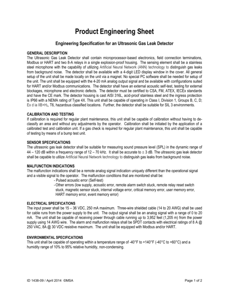
Product Engineering Sheet Engineering Specification for an Ultrasonic Gas Leak Detector GENERAL DESCRIPTION The Ultrasonic Gas Leak Detector shall contain microprocessor-based electronics, field connection terminations, Modbus or HART and two 8-A relays in a single explosion-proof housing. The sensing element shall be a stainless steel microphone with the capability of utilizing Artificial Neural Network (ANN) technology to distinguish gas leaks from background noise. The detector shall be available with a 4-digit LED display window in the cover. All general setup of the unit shall be made locally on the unit via a magnet. No special PC software shall be needed for setup of the unit. The unit shall be equipped with the 4-20 mA analog output signal and be available with configurations suited for HART and/or Modbus communications. The detector shall have an external acoustic self-test, testing for external blockages, microphone and electronic defects. The detector must be certified to CSA, FM, ATEX, IECEx standards and have the CE mark. The detector housing is cast AISI 316L, acid-proof stainless steel and the ingress protection is IP66 with a NEMA rating of Type 4X. This unit shall be capable of operating in Class I, Division 1, Groups B, C, D; Ex d ia IIB+H2, T6, hazardous classified locations. Further, the detector shall be suitable for SIL 3 environments. CALIBRATION AND TESTING If calibration is required for regular plant maintenance, this unit shall be capable of calibration without having to declassify an area and without any adjustments by the operator. Calibration shall be initiated by the application of a calibrated test and calibration unit. If a gas check is required for regular plant maintenance, this unit shall be capable of testing by means of a bump test unit. SENSOR SPECIFICATIONS The ultrasonic gas leak detector shall be suitable for measuring sound pressure level (SPL) in the dynamic range of 44 – 120 dB within a frequency range of 12 – 70 kHz. It shall be accurate to 3 dB. The ultrasonic gas leak detector shall be capable to utilize Artificial Neural Network technology to distinguish gas leaks from background noise. MALFUNCTION INDICATIONS The malfunction indications shall be a remote analog signal indication uniquely different than the operational signal and a visible signal to the operator. The malfunction conditions that are monitored shall be: - Pulsed acoustic error (Self-test) - Other errors (low supply, acoustic error, remote alarm switch stuck, remote relay reset switch stuck, magnetic sensor stuck, internal voltage error, critical memory error, user memory error, HART memory error, event memory error) ELECTRICAL SPECIFICATIONS The input power shall be 15 – 36 VDC, 250 mA maximum. Three-wire shielded cable (14 to 20 AWG) shall be used for cable runs from the power supply to the unit. The output signal shall be an analog signal with a range of 0 to 20 mA. The unit shall be capable of receiving power through cable running up to 3,952 feet (1,205 m) from the power supply using 14 AWG wire. The alarm and malfunction relays shall be SPDT contacts with electrical ratings of 8 A @ 250 VAC, 8A @ 30 VDC resistive maximum. The unit shall be equipped with Modbus and/or HART. ENVIRONMENTAL SPECIFICATIONS This unit shall be capable of operating within a temperature range of -40°F to +140°F (-40°C to +60°C) and a humidity range of 10% to 95% relative humidity, non-condensing. ID 1438-09 / April 2014 ©MSA Page 1 of 2 WARRANTY This unit shall have a two-year warranty. The manufacturer shall warrant this unit to be free from defects in workmanship and material under normal use and service within the warranty period from the date of shipment. SPECIFICATIONS AT A GLANCE Sensor Type: Ultrasonic (acoustic) gas leak detector Detector Frequency Range: 12 – 70 kHz Dynamic Range: 40 – 120 dB Accuracy: 3 dB Response Time: 1s Digital Display: Indicates sound pressure level, calibration prompts, and fault codes Electronics: Microprocessor-based Outputs: A. 0 to 20 mA analog signal 0 mA Start up, other errors 1 mA Pulsed acoustic error 3 mA Unit inhibit 4 – 12 mA: 40 – 120 dB 16 mA Warning: 20 mA Alarm B. Malfunction relay contact, 8 A @ 250 VAC, 8 A @ 30 VDC res. max. C. Alarm contact, 8 A @ 250 VAC, 8 A @ 30 VDC res. max. Calibration Mode: Initiated through Test and Calibration Unit 1701 Approvals: CSA, FM, ATEX, IECEx. CE Marking. HART registered, SIL 3 suitable Electrical Classification: Operating Temperature: Humidity Range: Input Power: Warranty: Cable Requirements: Class I, Division 1, Groups B, C, & D; Ex d ia IIB+H2 Gb T6 -40°F to +140°F (-40°C to +60°C) 10 to 95% relative humidity, non-condensing 24 VDC (nominal), 15 to 36 VDC Range, 250 mA max. Two years Three-wire shielded (14 to 20 AWG) ID 1438-09 / April 2014 ©MSA Page 2 of 2

![D257A Fixed-temperature (190°F [88°C]), Rate-of](http://s3.studylib.net/store/data/008909930_1-68ce451aaad20389934bcf47d8b73dbd-300x300.png)
