SAM * Simple/sAmple Machine
advertisement
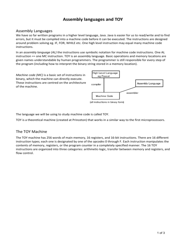
Assembly languages and TOY Assembly Languages We have so far written programs in a higher level language, Java. Java is easier for us to read/write and to find errors, but it must be compiled into a machine code before it can be executed. The instructions are designed around problem solving eg. IF, FOR, WHILE etc. One high level instruction may equal many machine code instructions. In an assembly language (AL) the instructions use symbolic notation for machine code instructions. One AL instruction == one MC instruction. TOY is an assembly language. Basic operations and memory locations are given names understandable by human programmers. The programmer is still responsible for every step of the program (including how to interpret the binary string stored in a memory location). Machine code (MC) is a basic set of instructions in binary, which the machine can directly execute. These instructions are centred on the architecture of the machine. The language we will be using to study machine code is called TOY. TOY is a theoretical machine (created at Princeton) that works in a similar way to the first microprocessors. The TOY Machine The TOY machine has 256 words of main memory, 16 registers, and 16-bit instructions. There are 16 different instruction types; each one is designated by one of the opcodes 0 through F. Each instruction manipulates the contents of memory, registers, or the program counter in a completely specified manner. The 16 TOY instructions are organized into three categories: arithmetic-logic, transfer between memory and registers, and flow control. 1 of 3 Instruction Representation – main memory only Summary of TOY instructions: OPCODE DESCRIPTION FORMAT PSEUDOCODE 0 halt - exit 1 add 1 R[d] ← R[s] + R[t] 2 subtract 1 R[d] ← R[s] - R[t] 3 and 1 R[d] ← R[s] & R[t] 4 xor 1 R[d] ← R[s] ^ R[t] 5 left shift 1 R[d] ← R[s] << R[t] 6 right shift 1 R[d] ← R[s] >> R[t] 7 load address 2 R[d] ← addr 8 Load 2 R[d] ← mem[addr] 9 store 2 mem[addr] ← R[d] A load indirect 1 R[d] ← mem[R[t]] B store indirect 1 mem[R[t]] ← R[d] C branch zero 2 if (R[d] == 0) pc ← addr D branch positive 2 if (R[d] > 0) pc ← addr E jump register - pc ← R[d] F jump and link 2 R[d] ← pc; pc ← addr Each TOY instruction consists of 4 hex digits (16 bits). The leading (left-most) hex digit encodes one of the 16 opcodes. The second (from the left) hex digit refers to one of the 16 registers, which we call the destination register and denote by d. The interpretation of the two rightmost hex digits depends on the opcode. Each opcode has a unique format. With Format 1 opcodes, the third and fourth hex digits are each interpreted as the index of a register, which we call the two source registers and denote by s and t. With Format 2 opcodes, the third and fourth hex digits (the rightmost 8 bits) are interpreted as a memory address, which we denote by addr. 15 14 13 12 11 10 9 8 Format 1 opcode destination (d) Format 2 opcode destination (d) 7 6 5 source (s) 4 3 2 1 0 source (t) address (addr) Notes Register 0 is always 0. Loads from mem[FF] are “standard input”- i.e. input data from the user. Stores to mem[FF] are “standard output”- i.e. output data to the user. Two instructions have no format listed ie. 0 and E. Consider the following examples. Instructions 0000, 0A14, 0BC7 would all halt execution. The last 3 hex digits are ignored. Instructions E500, E514, E5C7 would all change the value of the program counter to the contents of register 5. The last 2 hex digits are ignored. 2 of 3 Toy Programming Example 1: Addition (Adds 2 integers stored in main memory) Memory Address Contents 00 Pseudocode Explanation 0006 data The integer 6 is in memory address 00 01 0008 data The integer 8 is in memory address 01 10 8A00 R[A] ← mem[00] The integer 6 is copied to register A 11 8B01 R[B] ← mem[01] The integer 8 is copied to register B 12 1CAB R[C] ← R[A] + R[B] Integers 6 and 8 are added and the result (14) stored in register C 13 9C02 mem[02] ← R[C] The integer 14 is copied to memory address 02 14 0000 halt Stop execution Example 2: AND (determines whether an integer is odd (returns 1) or even (returns 0)) Memory Address Contents Pseudocode Explanation 10 7101 R[1] ← 0001 Register 1 set to 1 11 8AFF R[A] ← mem[FF] User input to register A 12 3BA1 R[B] ← R[A] & R[1] AND operation performed between contents of registers A and 1. Result to register B. 13 9BFF store mem[FF] ← R[B] Content of register B to standard output. 14 0000 halt Stop execution Example 3: LEFT SHIFT (multiplies a given integer by 8 (23)) Memory Address Contents 00 Pseudocode Explanation 0003 data The integer 3 is in memory address 00 10 8200 R[2] ← mem[00] The integer 3 is copied to register 2 11 8AFF R[A] ← mem[FF] User input to register A 12 5AA2 R[A] ← R[A] << R[2] Contents of register A left shifted by 3 13 9AFF store mem[FF] ← R[A] Content of register A to standard output. 14 0000 halt Stop execution 3 of 3


