Lab 10 - Mercury WWW Residents Home Pages
advertisement
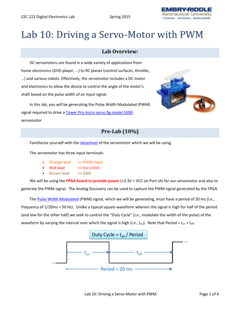
CEC 222 Digital Electronics Lab Spring 2015 Lab 10: Driving a Servo-Motor with PWM Lab Overview: DC servomotors are found in a wide variety of applications from home electronics (DVD player, …) to RC planes (control surfaces, throttle, …) and various robots. Effectively, the servomotor includes a DC motor and electronics to allow the device to control the angle of the motor’s shaft based on the pulse width of an input signal. In this lab, you will be generating the Pulse Width Modulated (PWM) signal required to drive a Tower Pro micro servo 9g model SG90 servomotor Pre-Lab (10%) Familiarize yourself with the datasheet of the servomotor which we will be using. The servomotor has three input terminals: Orange lead Red lead Brown lead => PWM input => Vcc (+5V) => GND We will be using the FPGA board to provide power (+3.3V = VCC on Port JA) for our servomotor and also to generate the PWM signal. The Analog Discovery can be used to capture the PWM signal generated by the FPGA. The Pulse Width Modulated (PWM) signal, which we will be generating, must have a period of 20 ms (i.e., frequency of 1/20ms = 50 Hz). Unlike a typical square waveform wherein the signal is high for half of the period (and low for the other half) we seek to control the “Duty Cycle” (i.e., modulate the width of the pulse) of the waveform by varying the interval over which the signal is high (i.e., ton). Note that Period = ton + toff. Duty Cycle = ton / Period … ton toff … Period = 20 ms Lab 10: Driving a Servo-Motor with PWM Page 1 of 4 CEC 222 Digital Electronics Lab Spring 2015 To generate the PWM signal we can design a counter which “wraps around” every 20 ms. Based on the desired Duty Cycle we can drive an output high for first part of the count and low for the remainder of the count. The BASYS2 board provides an onboard 50 MHz clock which can be used to drive our counter. Question 1. Using this 50MHz clock, how many clock cycles occur during a 1 ms interval? ______________________________________ Question 2. How many cycles are there in 20 ms using the same 50MHz clock? ____________________________________ Note that your counter should “wrap around” after this many cycles (i.e., counts)!! The SG90 servomotor will responds to varying duty cycles as follows: ton 1.00 ms 1.25 ms 1.50 ms 1.75 ms 2.00 ms Duty Cycle 1.0 / 20 = 5% 1.25 / 20 = 6.25% 1.5 / 20 = 7.5% 1.75 / 20 = 8.75% 2.0 / 20 = 10 % Motor Shaft Angle 0 deg 45 deg 90 deg 135 deg 180 deg Number of 50 MHz clock cycles ??? ??? ??? ??? ??? For this lab you will be entering a desired positive motor angle (in units of integer degrees) using the eight switches (SW7 … SW0) and then generate the appropriate PWM signal required to drive the servomotor to the desired motor shaft angle. Switches (SW7 … SW0) Desired Motor Shaft Angle 50 MHz clk VHDL code PWM Signal Servomotor One way to solve this problem is to determine the number of 50 MHz clock cycles (i.e., counts) corresponding to a desired motor angle (given in degrees). y=Mx+C where: y is in counts (i.e., the number of 50 MHz clock cycles), x is in degrees (desired angle), M is a scale factor in counts / degree, and C is the number of counts corresponding to a desired angle of 0 degrees. Question 3. What is the value of C in counts (i.e., number of 50 MHz clock cycles) and integer approximation of the coefficient M? __C = ??? counts___and_____M = ???_________________ Lab 10: Driving a Servo-Motor with PWM Page 2 of 4 CEC 222 Digital Electronics Lab Spring 2015 Question 4. What is the equation that describes the number of counts required to achieve a desired angle? Use integer values for M and C. ___ y = ??? x + ???_____ Main Experiment (90%) Step 1.a: Build a Counter To generate the PWM signal you will first need to create a VHDL file to count upwards for the duration of the signal’s period (i.e., 20 ms) and then restart at the end of that period. You should now have a counter that wraps around every 20 ms. HINT: See VHDL code for 16-bit counter from lecture on Wed, March 25. Step 1.b: Step 2: Modulate the Pulse Width Add a line of VHDL code which computes the count corresponding to a desired motor shaft angle (i.e., y = M x + C). The desired motor shaft is provided from the switches (SW7 … SW0). HINT: You might want to declare the signal “y” as type integer, also, the VHDL function conv_integer(??) will convert a variable of type STD_LOGIC_VECTOR to an integer value. y <= ??? * conv_integer(angle) + ?????; To vary the duty cycle add a segment of code to your existing counter that will accept an 8 bit vector (the desired angle in binary from SW7 to SW0) as an input, and output a ‘1’ for the duration of the pulse width with a “0” for the remaining period of time (HINT: if …). Count = 0 Desired angle in counts … HIGH … LOW Question 5. What is the Duty Cycle of the PWM for the following motor shaft angles: 0 degrees, 15 degrees, 30 degrees, and 90 degrees? Step 1.c: Power the servomotor using the FPGA (+3.3V = VCC on Port JA) and use your FPGA to drive it to desired shaft angles. Please recall the motor’s wiring convention, given above, as driving the PWM input with 5V will destroy the motor’s electronics!!! The GND from the Analog Discovery and the GND from the FPGA board must be connected to the GND of the servomotor!!! They must share a common GND. Lab 10: Driving a Servo-Motor with PWM Page 3 of 4 CEC 222 Digital Electronics Lab Spring 2015 Deliverables 1. Address all of the questions/tasks described in the pre-Lab (much of this should go into Section 2. Intro and/or Section 3. Theory within your lab report). 2. Formal Lab Report a. Show your commented VHDL code and explain how it works (place in the Appendix) b. Provide a screen capture of waveform for the following angles (place in Section 4. Results): i. 0 degrees, ii. 45 degrees, iii. 90 degrees, and iv. 135 degrees. c. Determine the Duty Cycle for each of the above motor shaft angles (Hint: You can measure this with the Analog Discovery). Do the Desired Motor Shaft Angle (entered via the 8 switches – SW7 … SW0) precisely match the actual motor’s shaft angle? d. Include photos of the Servo Motor at angles of (print the angle chart below and place your motor on top of it for each of the photos): i. 0 degrees, ii. 45 degrees, iii. 90 degrees, and iv. 135 degrees. 3. Extra-Credit (+10%): Based on your results from Deliverables Part 2b (above) update the values for “M” and “C” in your ___ y = M x + C_____ equation (and code). Use the provided VHDL code to display the “Desired Motor Shaft Angle” (entered via the 8 switches – SW7 … SW0) and demonstrate that your desired angle better corresponds to the actual motor’s shaft angle. Lab 10: Driving a Servo-Motor with PWM Page 4 of 4
