SPX HWB UNITS - LEAFLET
advertisement

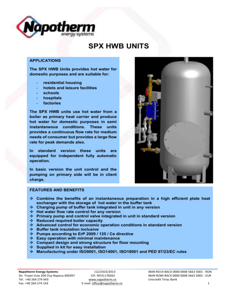
SPX HWB UNITS APPLICATIONS The SPX HWB Units provides hot water for domestic purposes and are suitable for: - residential housing hotels and leisure facilities schools hospitals factories The SPX HWB units use hot water from a boiler as primary heat carrier and produce hot water for domestic purposes in semi instantaneous conditions. These units provides a continuous flow rate for medium needs of consumer but provides a large flow rate for peak demands also. In standard version these units are equipped for independent fully automatic operation. In basic version the unit control and the pumping on primary side will be in client charge. FEATURES AND BENEFITS Combine the benefits of an instantaneous preparation in a high efficient plate heat exchanger with the storage of hot water in the buffer tank Charging pump of buffer tank integrated in unit in any version Hot water flow rate control for any version Primary pump and control valve integrated in unit in standard version Reduced required boiler capacity Advanced control for economic operation conditions in standard version Buffer tank insulation inclusive Pumps according to ErP 2009 / 125 / Ce directive Easy operation with minimal maintenance Compact design and strong structure for floor mounting Supplied in kit for easy installation Manufacturing under ISO9001, ISO14001, ISO18001 and PED 97/23/EC rules Napotherm Energy Systems Str. Traian Vuia 204 Cluj-Napoca 400397 Tel. +40 264 274 043 Fax. +40 264 274 143 J12/2423/2013 CIF: RO31178262 www.napotherm.ro E-mail: office@napotherm.ro IBAN RO14 BACX 0000 0008 5663 5001 - RON IBAN RO84 BACX 0000 0008 5663 5002 - EUR Unicredit Tiriac Bank 1 SPX HWB UNITS – FLOW DIAGRAM FOR STANDARD VERSION 1 2 3 4 5 6 7 8 9 plate heat exchanger control valve - 3 way primary pump pipe temperature sensor electric&control panel secondary pump flow controller buffer tank tank temperature sensor hot water 5 options on buffer tank: - termometer - electric heater 9 2 primary in 4 1 8 7 Dp+/- recirculation 3 6 primary out cold water SPX HWB unit drain MAXIMAL WORKING PARAMETERS PRIMARY SIDE temperature: 0 120 C SECONDARY SIDE pressure: 10 bar temperature: 850C pressure: 7 bar COMPONENTS GENERAL DATA PLATE HEAT EXCHANGER CONTROL VALVE PRIMARY PUMP SECONDARY PUMP plates and gaskets heat exchanger; frame in carbon steel painted plates: stainless steel AISI 316 grade; gaskets: NBR rubber 3 ports (mixing) seated control valve, motorized modulating actuator, 3 points control, 230 V single in-line pump, continuous variable speed comply with ErP 2009 / 125 / Ce directive single in-line pump comply with EU sanitary norms (bronze body) hydronic balancing valve, direct visual volume flow control FLOW CONTROLLER automatic sut-off bypass in parallel to main flow housing: brass; viewing: glass vertical storage vessel with inspection manhole BUFFER TANK carbon steel; inner lining: RC851 (alimentar quality) magnesium protection anode insulation: mineral wool 60 mm + PVC jacket (removable) PIPES CONTROLLER stainless steel on secondary / carbon steel, painted on primary side ELECTRIC BOX IP55 enclosure; 230 V, 50 Hz electronic, pre-programed; Modbus communication interface 2 SPX HWB UNITS – AVAILABLE MODELS&CAPACITIES FOR STANDARD VERSION primary side: 800C model SPX HWB 50 / 500 SPX HWB 75 / 500 SPX HWB 100 / 500 SPX HWB 150 / 500 SPX HWB 200 / 500 SPX HWB 75 / 750 SPX HWB 100 / 750 SPX HWB 150 / 750 SPX HWB 200 / 750 SPX HWB 100 / 1000 SPX HWB 150 / 1000 SPX HWB 200 / 1000 secondary side: 10-600C heat load flow free pressure storage capacity continuous flow rate peak flow rate (10 minutes) vessel charging time kW cm/h kPa liters cm/h cm/h minutes 50 75 1.27 1.90 22 16 500 500 0.86 1.29 3.86 4.29 35 23 100 2.53 23 500 1.72 4.72 17 150 3.32 19 500 2.59 5.58 12 200 4.43 22 500 3.45 6.45 9 75 1.90 16 750 1.29 5.79 35 100 2.53 23 750 1.72 6.22 26 150 3.32 19 750 2.59 7.08 17 200 4.43 22 750 3.45 7.95 13 100 2.53 23 1000 1.72 7.72 35 150 3.32 19 1000 2.59 8.59 23 200 4.43 22 1000 3.45 9.45 17 SELECTION: o Select unit heat load to obtain required hot water continuous flow rate at available boiler capacity o Select unit storage capacity to obtain required hot water peak flow rate for the desired vessel charging time Remarks: - for other primary side available temperatures please contact us - for other capacities please contact us 3 OVERAL DIMENSIONS model length width height WEIGHTS SPX HWB UNITS – DIMENSIONS&CONNECTIONS FOR STANDARD VERSION CONNECTIONS ELECTRIC CONNECTION primary side secondary side voltage power faze - V kW mm mm mm kg SPX HWB 50 / 500 SPX HWB 75 / 500 SPX HWB 100 / 500 SPX HWB 150 / 500 SPX HWB 200 / 500 1200 1200 650 650 1870 1870 165 165 1 1/4" 1 1/4" 2" 2" 1~ - 240 1~ - 240 0.18 0.18 1250 650 1870 170 1 1/2" 2" 1~ - 240 0.25 1250 650 1870 170 1 1/2" 2" 1~ - 240 0.30 1250 650 1870 175 1 1/2" 2" 1~ - 240 0.30 SPX HWB 75 / 750 SPX HWB 100 / 750 SPX HWB 150 / 750 SPX HWB 200 / 750 1400 800 1950 200 1 1/4" 2" 1~ - 240 0.18 1400 800 1950 205 1 1/2" 2" 1~ - 240 0.25 1450 800 1950 205 1 1/2" 2" 1~ - 240 0.30 1450 800 1950 210 1 1/2" 2" 1~ - 240 0.30 1400 800 2500 240 1 1/2" 2" 1~ - 240 0.25 1450 800 2500 240 1 1/2" 2" 1~ - 240 0.30 1450 800 2500 245 1 1/2" 2" 1~ - 240 0.30 SPX HWB 100 / 1000 SPX HWB 150 / 1000 SPX HWB 200 / 1000 4


