Determination of the length and position
of a non-visible object
TEP
5.4.20
-01
Related topics
Bremsstrahlung, characteristic X-radiation, law of absorption, mass absorption coefficient, and stereographic projection
Principle
This experiment provides training in determining the length and position of an object based on an X-ray
image. A metal pin that is embedded in a wooden block is used as the model. This experiment is also an
excellent preparatory exercise for demonstrating the principle of computed tomography.
Equipment
1
1
1
1
1
2
1
1
1
1
1
XR 4.0 expert unit 35kV
X-ray Plug-in module with W X-ray tube
XR 4.0 Implant model for X-ray photography
XR 4.0 fluorescent screen
XR 4.0 optical bench
Slide mount for optical bench, h = 30 mm
XR 4.0 Table with stem
Vernier caliper
XR 4.0 X-ray Adapter for digital camera 1/4""
XR 4.0 X-ray external optical bench
XR 4.0 X-ray slide for external optical bench
09057-99
09057-80
09058-07
09057-26
09057-18
08286-01
09824-01
03010-00
09057-15
09057-21
09057-29
Digital camera
This experiment is included in the upgrade set “XRI 4.0 X-ray imaging”.
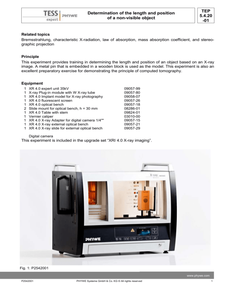
Fig. 1: P2542001
www.phywe.com
P2542001
PHYWE Systeme GmbH & Co. KG © All rights reserved
1
TEP
5.4.20
-01
Determination of the length and position
of a non-visible object
Tasks
1. X-ray the implant model in two planes that are shifted by 90° with regard to each other. Take a
picture of the image on the fluorescent screen.
2. Calculate the true length of the embedded metal pin by taking into account the magnification factor that needs to be determined.
3. Determine the spatial position of the metal
pin.
Procedure
Place the implant model directly in front of the fluorescent screen with both of them as far to the right
as possible on the optical bench. The distance between the front of the model and the outlet tube of
the X-ray plug-in unit is then approximately 30 cm.
Do not use a diaphragm tube for the irradiation.
Adjust an acceleration voltage UA = 35 kV and
an anode current IA = 1 mA.
Fasten the camera to the slide mount on the
optical bench.
Select the night mode and deactivate the
Fig. 2: Set-up
flash.
Either darken the room completely or cover
the device with the protective cover.
We recommend taking the picture with the automatic camera release (self-timer) in order to prevent
the camera from shaking.
Then, turn the implant model by 90° around its longitudinal axis and repeat the procedure.
Fig. 3: Pictures of the implant model; projection in the x,z-plane (left) and in the y,z-plane (right)
2
PHYWE Systeme GmbH & Co. KG © All rights reserved
P2542001
TEP
5.4.20
-01
Determination of the length and position
of a non-visible object
Theory and evaluation
Task 1: X-ray the implant model in two planes that
are shifted by 90° with regard to each other. Take
a picture of the image on the fluorescent screen.
Figure 3 shows example photos of the implant
model.
Task 2: Calculate the true length of the embedded
metal pin by taking into account the magnification
factor that needs to be determined.
Fig. 4: Random oblique position of the metal pin
Figure 4 shows a random oblique position of the
metal pin of the length l in a three-dimensional
space.
The length l of the pin with its ends P1 (x1,y1,z1) and P2 (x2,y2,z2) is:
l
x2 x1 2 y 2 y1 2 z 2 z1 2
l x2 l y2 l z2
(1)
Since the metal pin is irradiated by a conical bundle of X-rays and since it has a certain distance towards
the film plane, it is projected on the film plane in a magnified form. In order to be able to determine the
degree of magnification, the implant model is equipped with a metallic reference disk with a diameter of d
Fig. 5: Schematic representation of the projection of the metal pin in the x,z-plane (left) and in the y,z-plane (right)
= 30 mm. If the diameter of the disk projection on the film is d*, then the magnification is V = d*/d. As a
consequence, the true length of the metal pin is lw = l/V.
Figure 5 shows the projections of the metal pin for two planes of the implant model that are shifted by
90° with regard to each other. For the evaluation in accordance with figure 5, we recommend printing the
photo as large as possible and determining the corresponding lengths with the aid of a Vernier calliper.
www.phywe.com
P2542001
PHYWE Systeme GmbH & Co. KG © All rights reserved
3
TEP
5.4.20
-01
Determination of the length and position
of a non-visible object
As an alternative, a graphics program can be used.
Results (example):
The evaluation of the experiment example provided the following results:
lx = 52.0 mm, ly = 35.0 mm, lz = 71.0 mm and V = 46.0/30.0 mm = 1.533
Thus: lx = 33.9 mm, ly = 22.8 mm, lz = 46.3 mm
These value lead to: l = 61.74 mm and lw = 60.06 mm (the actual length of the metal pin (as manufactured) is 60.0 mm).
Task 3: Determine the spatial position of the metal pin.
Based on the projection lengths lx, ly, lz of l on the respective axes, the corresponding angles are calculated as follows:
ly
lx
l
; cos ; cos z
l
l
l
Using the values of the experiment example of task 2 (lx = 33.9 mm, ly = 22.8 mm, lz = 46.3 mm, and V =
46.0/30.0 mm = 1.533), the angles α, β, and γ are:
α = cos-1 lx / l = 0.54 → α = 53.6°
β = cos-1 ly / l = 0.40 → β = 67.7°
γ = cos-1 lz / l = 0.74 → γ = 39.6°
cos
4
PHYWE Systeme GmbH & Co. KG © All rights reserved
P2542001


