ME 462 - Lab 2 - Safe Digital Input and Output
advertisement

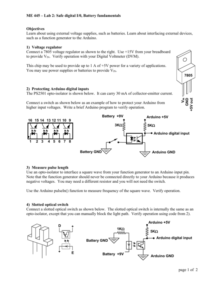
ME 445 – Lab 2: Safe digital I/0, Battery fundamentals Objectives Learn about using external voltage supplies, such as batteries. Learn about interfacing external devices, such as a function generator to the Arduino. 1) Voltage regulator Connect a 7805 voltage regulator as shown to the right. Use +15V from your breadboard to provide VIN. Verify operation with your Digital Voltmeter (DVM). This chip may be used to provide up to 1 A of +5V power for a variety of applications. You may use power supplies or batteries to provide VIN. 7805 VIN GND +5V out 2) Protecting Arduino digital inputs The PS2501 opto-isolator is shown below. It can carry 30 mA of collector-emitter current. Connect a switch as shown below as an example of how to protect your Arduino from higher input voltages. Write a brief Arduino program to verify operation. Battery +9V 16 15 14 13 12 11 10 9 3K Arduino +5V 5K Arduino digital input 1 2 3 4 5 6 7 8 Battery GND Arduino GND 3) Measure pulse length Use an opto-isolator to interface a square wave from your function generator to an Arduino input pin. Note that the function generator should never be connected directly to your Arduino because it produces negative voltages. You may need a different resistor and you will not need the switch. Use the Arduino pulseIn() function to measure frequency of the square wave. Verify operation. 4) Slotted optical switch Connect a slotted optical switch as shown below. The slotted optical switch is internally the same as an opto-isolator, except that you can manually block the light path. Verify operation using code from 2). Arduino +5V D + 1K Battery GND + E Battery +9V 5K Arduino digital input Arduino GND page 1 of 2 ME 445 – Lab 2: Safe digital I/0, Battery fundamentals 5) Protecting Arduino digital outputs Connect an LED to the isolated output as shown below as an example of how to protect your Arduino from higher output voltages. Verify operation. Arduino +5V Battery +9V 1500 isolated test point Arduino digital output 500 LED Battery GND 6) Measuring battery voltage We can’t use the Arduino to directly measure the voltage of the battery because the Arduino analog inputs are limited to be between 0V and 5V. Report: Design a circuit that will allow you to measure the battery voltage safely and include a circuit diagram in your report. Verify that your code works by checking your measurements with a multimeter. Hint: Lab 1 part 1 may be helpful. Report Include all of the items mentioned above and answer the following questions. 1) Your Arduino has a voltage regulator that reduces voltages on the pin labeled Vin to +5V. What is the range of voltages you can supply to the Arduino on Vin? 2) Some voltage regulators can produce a higher output voltage than the input voltage. Find a link to a regulator that performs this function. Hint: Pololu.com has a nice selection of these regulators. What are some of the drawbacks of this type of regulator? 3) In part 4, could you replace the battery with the 5V supply from your Arduino? Describe why or why not. Troubleshooting question: Pick the biggest problem you ran into while working on this lab and describe the problem in your report. Also provide the steps you followed to solve the problem. Think about how you could have determined what the problem was as quickly as possible and write about a method you would use to diagnose similar problems in the future. If you didn’t run into any problems, you write about what you think could have been a major issue. page 2 of 2


