Journal of Naval Architecture and Marine Engineering
June, 2014
http://dx.doi.org http://dx.doi.org/10.3329/jname.v11i1.15619
http://www.banglajol.info
PROSPECTS OF VIRTUAL OR COMPUTATIONALTOWING TANK
FACILITY FOR THE SHIPBUILDING INDUSTRY OFBANGLADESH
M. M. Rahaman1*, H. Akimoto2, H. Orihara3, N.M.G. Zakaria1 and S. Shabnam1
1
Department of Naval Architecture & Marine Engineering, Bangladesh University of Engineering & Technology, Dhaka-1000, Bangladesh,
*Email: mashiurrahaman@name.buet.ac.bd
2
Visiting Professor, Division of Ocean Systems Engineering (OSE), Korean Advanced Institute of Science & Technology (KAIST), Daejeon
304-701, Republic of Korea
3
Technical Research Center, Universal Shipbuilding Corporation, 1-3 Kumozu-Kokan-cho, Tsu 514-0398, Japan
Abstract:
Shipbuilding is on the verge of blooming into the major foreign revenue-earning industry in
Bangladesh. A number of export-oriented shipyards are developed to build different kinds of ships for
local and international clients. For designing a ship, model testing facilities are required not only to
predict power requirements but also to evaluate its performance in actual sea operation. At present,
Bangladesh does not have this facility. Also carrying out model testing is very expensive and time
consuming. Therefore, now-a-days a number of the shipyards in the world are using virtual or
computational towing tank facility. Due to improvement of solution algorithm for handling non-linear
problem and computational infrastructure, computational or virtual towing tank can be used as a
replacement of physical towing tank. In the present study, a numerical or computational towing tank
technique named WISDAM which is developed at The University of Tokyo, Japan is described with its
applicability in the perspective of Bangladesh shipbuilding industries.
Keywords: Computational fluid dynamics, RaNS, virtual towing tank, shipbuilding
1.
Introduction
Bangladesh has a strong background in building ships and was one of the leading centers of building inland and
ocean-going ships in Asia during the 15th and 17th century. Nature has adored Bangladesh with more than 200
rivers with a total length of about 22,155km plus an extensive coast line of the Bay of Bengal. Due to the long
history of maritime activities and also a natural geographical advantage, there are presently more than 100
shipbuilding and ship-repair yards to cater for the international and domestic needs in Bangladesh.
As a primary mode of transport, almost one fourth of the population of Bangladesh uses water transport. The
river network of Bangladesh extends to 8,300 km during the rainy season from 5,200 km during dry season.
Water transport is the cheapest mode of transport and therefore, it has become one of the most important modes
of transport for developing countries like Bangladesh. Various types of inland and coastal ships constructed
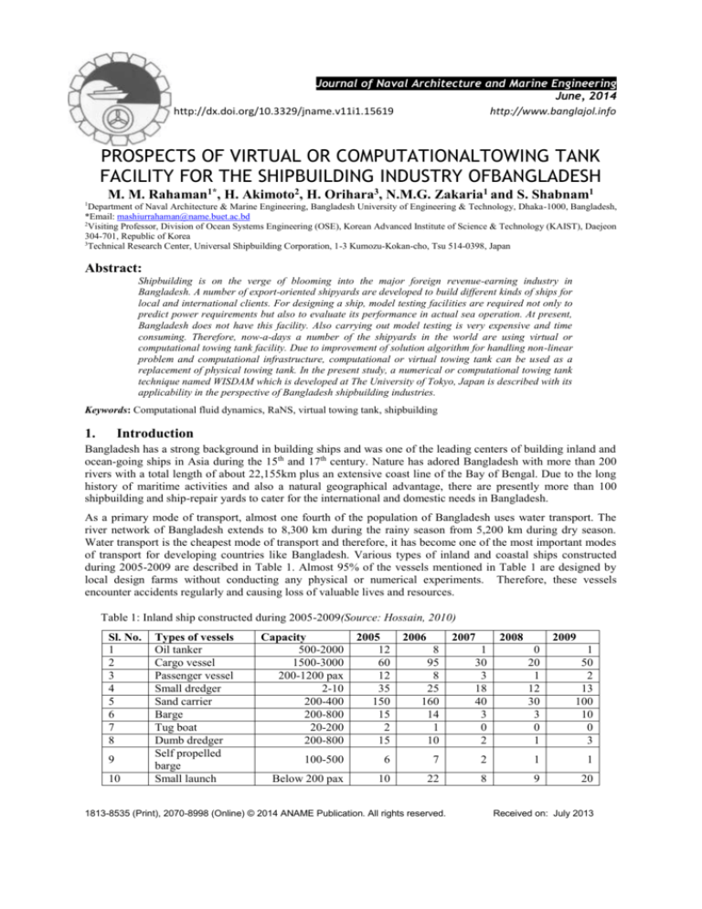
during 2005-2009 are described in Table 1. Almost 95% of the vessels mentioned in Table 1 are designed by
local design farms without conducting any physical or numerical experiments. Therefore, these vessels
encounter accidents regularly and causing loss of valuable lives and resources.
Table 1: Inland ship constructed during 2005-2009(Source: Hossain, 2010)
Sl. No.
1
2
3
4
5
6
7
8
9
10
Types of vessels
Oil tanker
Cargo vessel
Passenger vessel
Small dredger
Sand carrier
Barge
Tug boat
Dumb dredger
Self propelled
barge
Small launch
Capacity
500-2000
1500-3000
200-1200 pax
2-10
200-400
200-800
20-200
200-800
2005
12
60
12
35
150
15
2
15
100-500
Below 200 pax
2006
2007
2008
2009
8
95
8
25
160
14
1
10
1
30
3
18
40
3
0
2
0
20
1
12
30
3
0
1
1
50
2
13
100
10
0
3
6
7
2
1
1
10
22
8
9
20
1813-8535 (Print), 2070-8998 (Online) © 2014 ANAME Publication. All rights reserved.
Received on: July 2013
M. M. Rahaman, H. Akimoto, H. Orihara, , N.M.G. Zakaria,and S. Shabnam/Journal of Naval Architecture & Marine Engineering, 11(2014) 1-14
Since William Froude (ca. 1850) ship design is based on towing tank tests, which have been standardized
beginning in 1933 by procedures developed under the auspices of the International Towing Tank Conference
(ITTC) at its tri-annual meetings. The advent of computer technology and computational fluid dynamics (CFD)
methods offers an alternative to the traditional build and test design approach, i.e., simulation based design
(SBD). It has been conjectured that SBD will offer innovative approaches to design and out-of-the box concepts
with improved performance.
CFD for ship hydrodynamics is well developed with advanced capabilities for resistance and propulsion, seakeeping, and maneuvering as evidenced by the ship hydrodynamics CFD workshops and bi-annual Office of
Naval Research (ONR) Symposiums on Naval Hydrodynamics (SNH). One of the leading ship hydrodynamics
CFD codes and of present interest is WISDAM, which has been developed at The University of Tokyo, Japan.
The capabilities of ship hydrodynamics CFD codes have largely been demonstrated mimicking typical towing
tank tests using the experimental data for validation of the simulations, including both global and local flow
variables (Longo et.al. 2007). Once validated, CFD thus far has largely been used for design analysis, but with
its current interdisciplinary capability including global optimization methods(Campana et. al., 2006) and
emerging multidisciplinary capability it assures in short time the reality of SBD. Recently, CFD has shown its
usefulness inconceptual design for high-speed sealift concepts (Stern et. al., 2006). Herein, the concept of a
computational towing tank is implemented to show that CFD and SBD have a potential to aid the design
process. The idea of a numerical towing tank is not new, as the name has been used for an annual European
workshop, most recently Numerical Towing Tank Symposium (NUTTS); however, herein we demonstrate
different possibilities and the full potential of the concept. It will be shown that both resistance and propulsion
tests can be conducted in a unique and efficient manner not possible or highly difficult using a physical towing
tank.
2. Challenges in Maritime Design
Hydrodynamic performance of ships is one of the most decisive factors for quality, economy and safety in
waterborne transportation. Analysis and optimization of the hydrodynamic performance or behavior of ships at
sea is a lengthy, time consuming process, sparsely supported by modern computational techniques. This element
which is prominent in the design process for ships and maritime structures is a limiting factor for the overall
performance of the maritime industry. Improving this situation will clearly uplift the performance of
shipbuilding and overall maritime industry. Being able to fix design constraints for a typical one-of-a-kind
product early in the design process allows for a substantially improved accuracy in the production planning and
cost evaluation processes. Improving global design and optimization processes will thus have direct as well as
indirect-via a shortened production lead time-influences on the products and production costs.
3. Present Status of Maritime CFD
Numerical treatment of fluid flow for maritime crafts are much more complex than other types of vehicle
because of special environmental treatments associated with its operation for example sailing at a free surface.
Academic and research organizations have devoted long potential on numerical simulations in the maritime field
accompanying traditional model testing.
Numerical or computational fluid dynamics (CFD) methods have been developed mostly with a dedicated field
of application in mind. Examples are potential theory based strip methods, wave resistance or propeller codes.
Concentration on particular applications has caused a large variety of methods, based on different methods and
technologies to be developed in the past. Today’s developments are without any doubt helpful tools to analyze
hydrodynamic behavior, but it must be clearly noted that they hardly allow for integrated analysis of a variety of
different objectives. This will still call for sequential process applying a variety of different methods and suffer
from often complex data exchange and conversion process.
Experimental or model tank testing has a long tradition and, due to its history and experience gained with
calibration results, a wide acceptance in terms of accuracy of predicted results. Today experimental results are
still the measure with which to compare all numerical results. Although there have been significant
improvements in the quality or accuracy of CFD predictions over time, it may be noted here that there is still a
lack of accuracy associated with many numerical flow predictions methods.
4. WISDAM Technique
Unsteady Reynolds averaged Navier-Stokes based WISDAM codes developed by Orihara et.al. (2000, 2002,
2003 and 2004) for predicting hydrodynamic characteristics of practical ship hull form with the capability of
Prospects of virtual or computational towing tank facility for the shipbuilding industry of Bangladesh
2
M. M. Rahaman, H. Akimoto, H. Orihara, , N.M.G. Zakaria,and S. Shabnam/Journal of Naval Architecture & Marine Engineering, 11(2014) 1-14
handling 6 (six) DOF motions. At present, WISDAM codes are used by IHI Corporation, Japan and other
renowned shipyards and shipbuilding industry in Japan and Republic of Korea.
4.1
Co-ordinate system
WISDAM method uses three different sets of orthogonal co-ordinate systems, space-fixed o- xyz , body-fixed
O-XYZ and translation co-ordinate system O- X 0Y0 Z 0 shown in Fig.1. These co-ordinate systems relates in the
following manner.
X 0 , Y0 , Z 0 T
X , Y , Z T
x, y, z rc t
T
E, ,
. X 0 , Y0 , Z 0
Here, Euler angles,
E , ,
, , which is transformation matrix as
cos cos
cos sin
sin
sin sin cos cos sin sin sin sin cos cos sin cos
cos sin cos sin sin cos sin sin sin cos cos cos
and
(1)
T
rc t is the position vector of the center of gravity of the ship defined in o- xyz .
(2)
(3)
Fig. 1: Definition of co-ordinate systems and Euler angles, Orihara [2003]
4.2
Governing equations
Reynolds averaged Navier-Stokes equation and the continuity equations are solved on the overlapping grid
system using finite volume method. In non-inertial co-ordinate system, the RaNS and continuity equations are
expressed in the integral form for a control volume Ω as;
u
dV TdS KdV
t
u.dS 0
(4)
(5)
where u is the fluid velocity vector,
the inertial effect on fluid.
T is the fluid stress tensor and K is the body force vector accounting for
All of the fluid variables are made dimensionless with respect to constant reference velocity 𝑈0 , ship length 𝐿
and the density of fluid. The dimensionless parameters, Reynolds number ( Re ) and Froude number ( Fn ) are
defined as
Re
U0L
where and
Fn
U0
gL
(6)
g are the dynamic viscosity of fluid and the gravitational acceleration respectively.
Prospects of virtual or computational towing tank facility for the shipbuilding industry of Bangladesh
3
M. M. Rahaman, H. Akimoto, H. Orihara, , N.M.G. Zakaria,and S. Shabnam/Journal of Naval Architecture & Marine Engineering, 11(2014) 1-14
The fluid stress tensor
T uu I
T is expressed as
1
T
u u u u
Re
(7)
T
where I is the identity tensor, is the gradient operator, . denotes the transport operator, uu is the
Reynolds stress and is the non-dimensionalized pressure excluding the hydrostatic component defined as
z
(8)
p 2
Fn
where z is the vertical up and p is the static pressure of the fluid.
The body force vector
K is given as follows
K 2 u r
d
dV
r
dt
dt
(9)
where is the angular velocity vector about body fixed co-ordinate system O-XYZ, r is the position vector
defined in O-XYZ, V is the translating velocity of the origin of the body-fixed system. The term in the righthand side of eq. (9) are the Coriolis force, the centrifugal force, the angular acceleration force and the translating
acceleration force respectively.
4.3
Free-surface treatment
Treatment of free-surface is based on density function method. In WISDAM, solving the following transport
equation of density function m satisfies the kinematic condition of free surface.
m
dV dS .u m
t
where u is the velocity vector of fluid, density function
1
0
m
(10)
m defined in the entire computational region as,
in fluid region
in external region
(11)
Equation (10) is discretized by finite-volume method and solved in a time marching way. The location of free
surface is as the iso-surface of m =0.5. Extrapolation of pressure and velocity components above the free
surface satisfies the free surface dynamic condition.
To evaluate turbulent viscosity in the flow field, blended Baldwin-Lomax zero equation model and Dynamic
Sub-Grid Scale (DSGS) model is used. The local turbulent velocity is determined by weighted average of these
two models.
4.4
Computational domains and grids
For the implementation of the interaction of incident waves and the resultant ship motions, overlapping grid
systems are employed in WISDAM. By employing overlapping grid systems, the total simulation domains
(shown in Fig.2) are divided into two as inner solution domain and outer solution domain. The inner solution
domain covers the vicinity of the hull surface, where high resolution mesh (C-H type for half hull; O-H type for
full hull) is generated to capture the free surface. The outer solution domain is located at a several ship length
away from the hull surface. In each solution domain, structured computational mesh is generated independently
using PointwiseV16.04R3. To avoid green water loading on deck, the hull surface is extended in upward
direction to cover the deck.
Prospects of virtual or computational towing tank facility for the shipbuilding industry of Bangladesh
4
M. M. Rahaman, H. Akimoto, H. Orihara, , N.M.G. Zakaria,and S. Shabnam/Journal of Naval Architecture & Marine Engineering, 11(2014) 1-14
Hull surface
Inner domain
Inflow boundary
Outer domain
Fig.2: Computational domains of WISDAM
4.5
Flow simulation
The motion of the ship is simultaneously solved by combining the equations of motions of the ship body with
the flow computation. Since, non-deforming grid is used, the flow computation in the near filed is performed on
the non-inertia co-ordinate system fixed to the body of the ship. The effect of the ship motion on the flow
solution is taken into account by adding inertia forces as the body force K in the right-hand side of Eq. (4).
4.6
Wave generation
In WISDAM, incident waves are generated based on linear wave theory by which wave velocity potential is
derived as
Ac
cosh d z
sin x cos y sin t
sinh d
(12)
Further, if we assume that water depth tends to infinity, then the flow velocity
u and arbitrary quantity in
the space-fixed co-ordinate system can be described as,
z
u w cos Ae cos x cos y sin t
u vw sin Aez cos x cos y sin t
w ez sin x cos y sin t
A
w
2 A2
2
w Acez sin x cos y sin t
(13)
e 2z
(14)
Here,
uw
, vw
, ww
x
y
z
w = static pressure of incident waves.
Incident waves are generated on outer solution domain. When waves enter into inner solution domain, boundary
conditions with the interaction of
uw , vw , ww and uniform velocity U 0 ,0,0 transform the formula into the
following.
Prospects of virtual or computational towing tank facility for the shipbuilding industry of Bangladesh
5
M. M. Rahaman, H. Akimoto, H. Orihara, , N.M.G. Zakaria,and S. Shabnam/Journal of Naval Architecture & Marine Engineering, 11(2014) 1-14
z
u U 0 cos Ae cos x cos y sin t
u v sin Aez cos x cos y sin t
w
Aez sin x cos y sin t
(15)
Moreover, the relationship between space-fixed co-ordinate, o- xyz and translation co-ordinate O- X 0Y0 Z 0 is
expressed as
U 0Tacc
x X 0 U 0t
2
Y0
y
z
Z
0
(16)
5. Application of WISDAM Technique
Computational results of WISDAM were already validated with towing tank experimental results for different
types of ships at various Froude’s number with various conditions of wave length-ship length ratio, λ/L and
wave amplitude-ship length ratios, ζ/L in regular and irregular head and oblique waves. All calculations were
performed with 2 (two) degrees of freedom i.e. heave and pitch free conditions. In this section, some of the
results are presented to show the capability of WISDAM and its applicability to use in initial ship design
process.
5.1
Ship model
Numerical or computational results of container ship models named SR108, KCS; tanker ship model SR221C;
bow-series model M58F0, M58F1 are presented.
5.1.1 Container ship model
Ship model SR108 was designed by National Maritime Research Institute (NMRI), Japan and KCS is developed
by Korean Ocean Research and Development Institute (KORDI).Figs. 3(a) and 3(b) show the body plan of
SR108 and KCS respectively.
(a)
(b)
Fig. 3: Body plan of (a) SR108 and (b) KCS
5.1.2 Tanker ship model
Fig. 4 shows locations of pressure point pick-up for validation of local pressure on the body plan of a tanker ship
model, SR221C.
Prospects of virtual or computational towing tank facility for the shipbuilding industry of Bangladesh
6
M. M. Rahaman, H. Akimoto, H. Orihara, , N.M.G. Zakaria,and S. Shabnam/Journal of Naval Architecture & Marine Engineering, 11(2014) 1-14
Fig.4: Locations of pressure pick-ups on tanker ship model SR221C, Orihara [2004]
5.1.3 Bow-series model
The M58 series consists of two models with different bow shapes, different in the hull portion above the design
water line (DWL). The bow shape of M58F1 differs from that of the original form (M58F0) in both the bow
profile and body plan ahead of S.S. and 9 ½ as shown in Fig. 5. M58F1 has an extremely long-protruding bow
shape which is expected to reduce added resistance in waves by reducing the entrance angle of the waterline
above DWL.
Fig.5: Body plans and bow profiles of M58 series models, Orihara [2003]
5.2
Ship motions in regular head wave
Fig. 6 shows the comparison of Response Amplitude Operator (RAO) of heave and pitch motion of SR108 at
Froude No., Fn=0.25 and ζ/L= 0.01 in head wave. The amplitude of heave and pitch motions are made
dimensionless with respect to wave amplitude and wave slope respectively. The amplitudes of the ship’s
motions are obtained by harmonic analysis of computed time histories of ship’s motion, where the first
harmonic is taken as the motion amplitude. Fig. 7 shows the comparison of time history of heave and pitch
motion for KCS at Fn=0.33, λ/L=1.33 and ζ/L= 0.0112 in head wave. Figs.8 and 9 show the comparison of
RAO’s of heave and pitch motion for M58 model series at F n=0.224 and for SR221C model series Fn=0.15 in
head wave respectively. It is seen from Figs.6 ~ 9 that WISDAM predicted ship motions accurately with towing
tank experiments for all the cases. The possible reason for accurate predictions of ship motions is the exact
treatment of the hull surfaces and the free surface boundary conditions in WISDAM. Since ship’s motion has a
noticeable effect on the surface pressures, this copes with the good agreement of calculated surface pressures
with experimental data.
Prospects of virtual or computational towing tank facility for the shipbuilding industry of Bangladesh
7
M. M. Rahaman, H. Akimoto, H. Orihara, , N.M.G. Zakaria,and S. Shabnam/Journal of Naval Architecture & Marine Engineering, 11(2014) 1-14
Since the uncertainty of the experimental data is not evaluated, in general, it may be said that it is 1% of the
amplitude of the incident wave for the amplitude of heave motions and within 1% of the mean slope of the
incident wave for the amplitude of pitch motions.
Fig.6: Response amplitude operator of heave and pitch motion of SR108 at F n=0.25 and ζ/L= 0.01 in head wave
Fig.7: Comparison of time history of heave and pitch motion for KCS at Fn=0.33, λ/L=1.33 and ζ/L= 0.0112 in
head wave
Fig.8: Comparison of RAO’s of heave and pitch motion for M58 model series at F n=0.224 in head
wave,Orihara [2003]
Prospects of virtual or computational towing tank facility for the shipbuilding industry of Bangladesh
8
M. M. Rahaman, H. Akimoto, H. Orihara, , N.M.G. Zakaria,and S. Shabnam/Journal of Naval Architecture & Marine Engineering, 11(2014) 1-14
P6 / ρ g ζA
P5 / ρ g ζA
P4 / ρ g ζA
Fig.9: Comparison of RAO’s of heave and pitch motion for SR221C at Fn=0.15 in head wave
t.(U/L)
Fig.10: Comparison of time history of surface pressures on tanker ship model SR221C in regular head waves at
Fn=0.150, λ/L=0.4 and ζA/L=0.01, Orihara [2004]
Prospects of virtual or computational towing tank facility for the shipbuilding industry of Bangladesh
9
P6 / ρ g ζA
P5 / ρ g ζA
P4 / ρ g ζA
M. M. Rahaman, H. Akimoto, H. Orihara, , N.M.G. Zakaria,and S. Shabnam/Journal of Naval Architecture & Marine Engineering, 11(2014) 1-14
t.(U/L)
P6 / ρ g ζA
P5 / ρ g ζA
P4 / ρ g ζA
Fig.11: Comparison of time history of surface pressures on tanker ship model SR221C in regular head waves at
Fn=0.150, λ/L=1.00 and ζA/L=0.01, Orihara [2004]
t.(U/L)
Fig.12: Comparison of time history of surface pressures on tanker ship model SR221C in regular head waves at
Fn=0.150, λ/L=1.6 and ζA/L=0.01, Orihara [2004]
Time history of local pressure is evaluated at six points on the flare region of tanker model SR221C, shown in
Fig. 4. Locations of points are chosen based on the high pressure region on the bow flare. Local pressure is nondimensionalized based on density of water, ρ, gravitational acceleration, g and local wave amplitude.
Prospects of virtual or computational towing tank facility for the shipbuilding industry of Bangladesh
10
M. M. Rahaman, H. Akimoto, H. Orihara, , N.M.G. Zakaria,and S. Shabnam/Journal of Naval Architecture & Marine Engineering, 11(2014) 1-14
Comparison of time histories of hull surface pressures are shown in Figs.10~12 for the cases λ/L= 0.4, 1.0 and
1.6 at Fn=0.150 and ζA/L=0.01. In present study, the pressures are defined as the difference relative to the
atmospheric pressures. So, the pressure is zero when the pressure gauges exposed in the air. Since the gauges are
place above the still water level, all the gauges experienced the exposure in the air for all the cases of wave
lengths. As can be seen in Figs. 10 ~12, calculated results are in good agreement with the experimental data.
The calculated histories capture time histories from triangular shape to rounded one with the increase in the
length of incident waves.
5.3
Ship motions in regular oblique wave
Figs. 13(a) ~ 13(b) show the comparison of Response Amplitude Operator (RAO) of heave and pitch motion for
SR108 at Fn=0.25 and ζ/L= 0.01 in 120 deg. oblique wave. Present numerical method, WISDAM predicted peak
value of heave and pitch motions well with experiments.
Experiment
Heave (non-dimensional)
Heave (non-dimensional)
(a)
(b)
)
Experiment
CFD
Wave length/ship length, λ/L
CFD
Wave length/ship length, λ/L
Fig.13: Response amplitude operator for SR108 at Fn=0.25 and ζ/L= 0.01 in 120 deg. oblique wave; (a) heave
motion and (b) pitch motion
5.4
Added resistance in regular head wave
Fig. 14 shows the comparison of Response Amplitude Operator (RAO)’s of added resistance for SR108 at
Fn=0.250, 0.275and 0.300 in waves of ζ/L= 0.01. Although, some discrepancies can be seen in Fig. 14, the
computed results agree well with experimental results in all the cases.
Fig. 15 shows the comparison of time history of total drag for ship model KCS at Fn=0.26, λ/L=2.00 and ζ/L=
0.0167. It is seen from Fig. 15 that WISDAM under predicted the total drag for case of KCS. The possible
reasons for this discrepancy in total resistance are due to the way of ship model towed during experiment. In the
experiment, the model is mounted in two posts. Therefore, the system is not completely stiff. The ship may
surge when it moves through waves. So, during experiment the action is like the model is towed in a spring.
However, in numerical method, the model is towed in an ideal stiff setup. It means the possibility of surging
during numerical simulation is zero. The result could be that the shape of the time series for the resistance
obtained with different systems could be different and that the signals, therefore cannot be directly compared at
a given time instance.
(Simonsen et. al. , 2008) compared their numerical method (RaNS based CFD code CFDSHIP-IOWA) with the
same experimental results of present analysis and a strong disagreement was observed for resistance data. They
concluded that the data may be deficient.
Prospects of virtual or computational towing tank facility for the shipbuilding industry of Bangladesh
11
M. M. Rahaman, H. Akimoto, H. Orihara, , N.M.G. Zakaria,and S. Shabnam/Journal of Naval Architecture & Marine Engineering, 11(2014) 1-14
Fig.14: Comparison of RAO’s of added resistance for SR108 at Fn=0.250, 0.275and 0.300 in waves of ζ/L=
0.01
Fig.15: Comparison of time history of total drag coefficient, CT for KCS at Fn=0.26, λ/L=2.00 and ζ/L= 0.0167
in head wave
Prospects of virtual or computational towing tank facility for the shipbuilding industry of Bangladesh
12
M. M. Rahaman, H. Akimoto, H. Orihara, , N.M.G. Zakaria,and S. Shabnam/Journal of Naval Architecture & Marine Engineering, 11(2014) 1-14
Comparison of RAO’s of added resistance for SR221C at F n=0.26 in head wave is shown in Fig.16. Though the
predicted results slightly overestimate the experimental data, the calculated results agree well with the
experimental results.
Fig.16: Comparison of RAO’s of added resistance for SR221C at Fn=0.26 in head wave
Fig.17: Comparison of RAO’s of added resistance for M58 model series at Fn=0.224 in head wave, Orihara
[2004]
Prospects of virtual or computational towing tank facility for the shipbuilding industry of Bangladesh
13
M. M. Rahaman, H. Akimoto, H. Orihara, , N.M.G. Zakaria,and S. Shabnam/Journal of Naval Architecture & Marine Engineering, 11(2014) 1-14
Fig. 17 shows the comparison of added resistance for M58 model series at F n=0.224 in head wave. Although,
some calculations slightly over predicts the experiment, the relative magnitude of added resistance between the
models i.e. the reduction in added resistance due to the bow shape modifications is well predicted. For all the
wave length cases, the computed added resistance for M58F1 is smaller than for M58F0 by nearly the same
amount as measured difference in added resistance in the experiment.
6. Conclusion
A RaNS based virtual or computational towing tank technique WISDAM is described. The accuracy of the
predictions is validated by comparing time histories and Response Amplitude Operator (RAO)of surface
pressures, ship motions and added resistance. Two container ship models named SR108 and KCS, tanker ship
model SR221C and bow-series models M58F0 and M58F1 are chosen for assessment. It is seen that WISDAM
can predict the ship motions and added resistance well with experiments for these ships. Although the degree of
accuracy of predictions is not fully satisfactory but the present CFD results show a superior availability than
other existing analytical methods.
Also, since at present physical experimental facilities for maritime industry like towing tank are not available in
Bangladesh, WISDAM can be a better alternative tool for the assessment of ship performance in waves and the
development of hull forms with superior performance in waves.
Acknowledgement
This research was supported by WCU (World Class University) program through the National Research
Foundation of Korea funded by the Ministry of Education, Science and Technology (R31-2008-000-10045-0).
References
Campana, E. F., Peri, D., Tahara, Y., and Stern, F. (2006): Shape optimization in ship hydrodynamics using
computational fluid dynamics, Computational Methods Appl. Mech. Eng., 196(1–3), pp. 634–651.
http://dx.doi.org/10.1016/j.cma.2006.06.003
Hossain, K.A.(2010): Evaluation of potential, prospects and challenge of Bangladesh shipbuilding in the light of
global context, M.Sc. Engg. Thesis, Department of Naval Architecture & Marine Engineering, Bangladesh
University of Engineering & Technology (BUET), Dhaka-1000, Bangladesh
Longo, J., Shao, J., Irvine, M., and Stern, F. (2007): Phase-averaged PIV for the nominal wake of a surface ship
in regular head waves, ASME J. Fluid Engg., 129(5), pp. 524–540.http://dx.doi.org/10.1115/1.2717618
Orihara, H. and Miyata, H. (2000): Numerical simulation method for flows about a semi-planing boat with a
transom stern, Journal of Ship Research, vol. 44, No.3, pp.170-185.
Orihara, H. (2002): Validation of numerical method for predicting hydrodynamic characteristics of a high-speed
ship, 24th Symposium on Naval Hydrodynamics, Fukuoka, Japan.
Orihara, H. and Miyata, H. (2003): Evaluation of added resistance in regular incident waves by computational
fluid dynamics motion simulation using an overlapping grid system, Journal of Marine Science and Technology,
vol. 6, pp. 47-60.http://dx.doi.org/10.1007/s00773-003-0163-5
Orihara, H. and Miyata, H. (2004): CFD performance simulation method for the prediction of life cycle fuel
consumption, 25th Symposium on Naval Hydrodynamics, Newfoundland, Canada.
Simonsen, C., Otsen, J. and Stern, F. (2008): EFD and CFD for KCS heaving and pitching in regular head
waves, Proceedings of 27th Symposium on Naval Hydrodynamics, Seoul, Korea, pp. 302-320.
Stern, F., Carrica, P. M., Kandasamy, M., Gorski, J., O'Dea, J., Hughes, M.,Miller, R., Hendrix, D., Kring, D.,
Milewski, W., Hoffman, R., and Gary, C. (2006): Computational hydrodynamic tools for high-speed cargo
transports, The SNAME Transactions, 114, pp. 55–81.
Prospects of virtual or computational towing tank facility for the shipbuilding industry of Bangladesh
14


