6. EXAM NO. 1 (Due 3/15/2014 by email)
advertisement
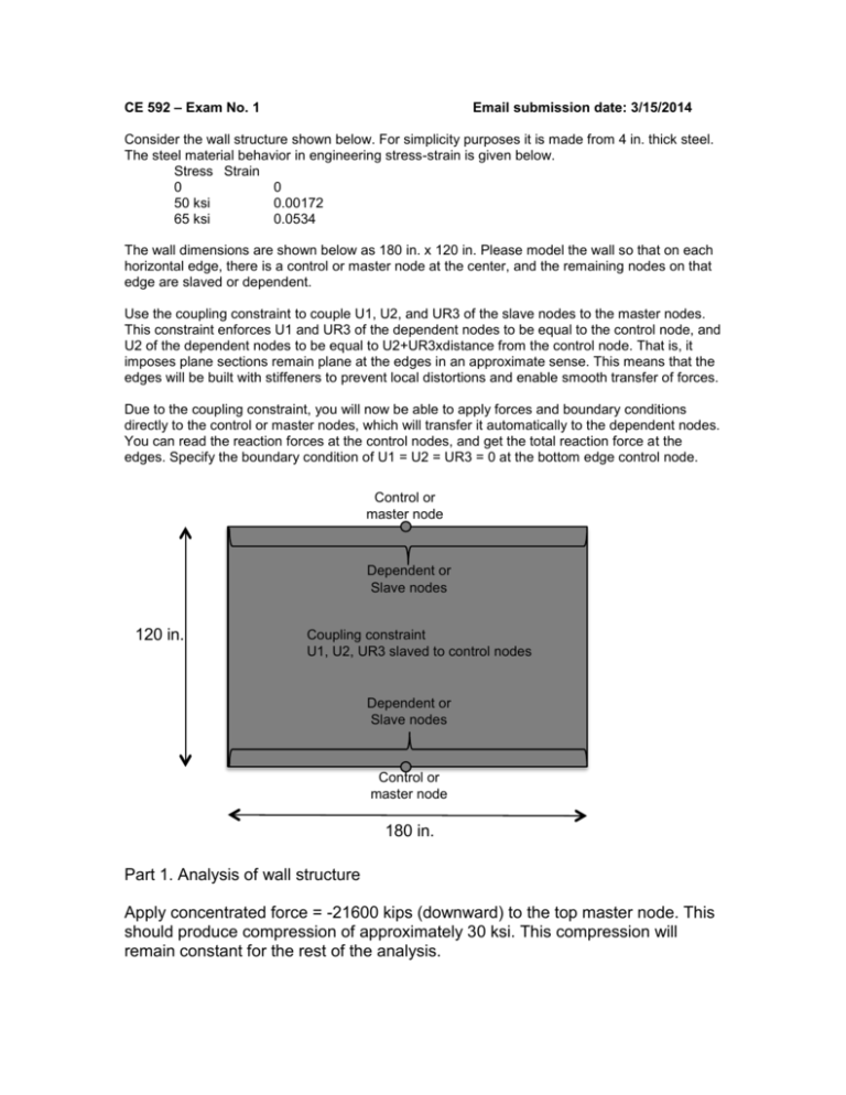
CE 592 – Exam No. 1 Email submission date: 3/15/2014 Consider the wall structure shown below. For simplicity purposes it is made from 4 in. thick steel. The steel material behavior in engineering stress-strain is given below. Stress Strain 0 0 50 ksi 0.00172 65 ksi 0.0534 The wall dimensions are shown below as 180 in. x 120 in. Please model the wall so that on each horizontal edge, there is a control or master node at the center, and the remaining nodes on that edge are slaved or dependent. Use the coupling constraint to couple U1, U2, and UR3 of the slave nodes to the master nodes. This constraint enforces U1 and UR3 of the dependent nodes to be equal to the control node, and U2 of the dependent nodes to be equal to U2+UR3xdistance from the control node. That is, it imposes plane sections remain plane at the edges in an approximate sense. This means that the edges will be built with stiffeners to prevent local distortions and enable smooth transfer of forces. Due to the coupling constraint, you will now be able to apply forces and boundary conditions directly to the control or master nodes, which will transfer it automatically to the dependent nodes. You can read the reaction forces at the control nodes, and get the total reaction force at the edges. Specify the boundary condition of U1 = U2 = UR3 = 0 at the bottom edge control node. Control or master node Dependent or Slave nodes 120 in. Coupling constraint U1, U2, UR3 slaved to control nodes Dependent or Slave nodes Control or master node 180 in. Part 1. Analysis of wall structure Apply concentrated force = -21600 kips (downward) to the top master node. This should produce compression of approximately 30 ksi. This compression will remain constant for the rest of the analysis. Subject the structure to cyclic loading equivalent to 1% story drift. The displacement history will correspond to +1%, 0, -1%, 0, +1% story drift. Conduct the analysis for both isotropic and kinematic hardening material models. Present the results in the context of hand calculations of strength and lateral load capacity. Confirm that the material is following the effective stress-effective strain curve at some selected locations. Confirm the evolution of the stress states on the loading surfaces if possible. Part 2. Analysis of wall structure with perforation Change the model to include a hole of diameter equal to 40 in. at the center of the wall. As mentioned earlier, this perforation has been made to facilitate pipe penetration into the wall. Make sure that the mesh size you use is appropriate for the application. Apply concentrated force = -21600 kips (downward) to the top master node. This compression will remain constant for the rest of the analysis. Subject the structure to cyclic loading equivalent to 1% story drift. The displacement history will correspond to +1%, 0, -1%, 0, +1% story drift. Conduct the analysis for both isotropic and kinematic hardening material models. Present the results, and compare them with the analysis of the wall without perforation. Perform hand calculations to compare with the calculated strength and lateral load capacity of the wall with holes. Discuss the effect of the hole on the stiffness and strength of the structure, and what advice (design recommendations) you would give to an engineer who would only perform elastic analysis, and hand calculations as per the codes. That is what reduction in stiffness and strength the designer should assume and what would be the basis of these recommendations. Are your recommendations valid for all hole diameters? If not, then provide the limiting range for your recommendation. Confirm that the material is following the effective stress-effective strain curve at some selected locations. Confirm the evolution of the stress states on the loading surfaces if possible.


