The Appendix IV and V - P
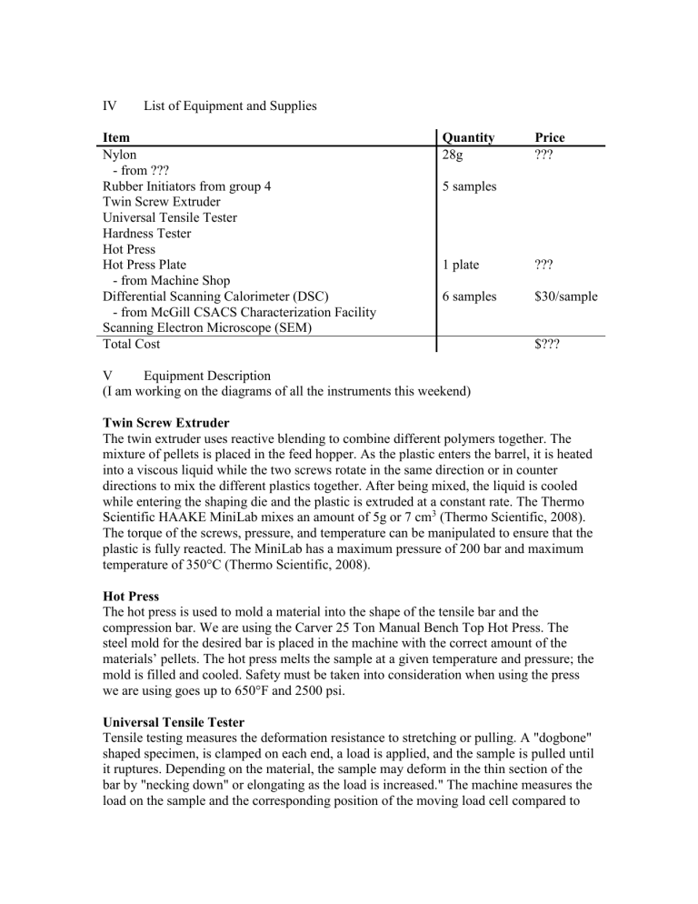
IV List of Equipment and Supplies
Item Quantity Price
Nylon
- from ???
Rubber Initiators from group 4
Twin Screw Extruder
Universal Tensile Tester
Hardness Tester
Hot Press
Hot Press Plate
- from Machine Shop
Differential Scanning Calorimeter (DSC)
- from McGill CSACS Characterization Facility
Scanning Electron Microscope (SEM)
Total Cost
V Equipment Description
28g
5 samples
1 plate
6 samples
???
???
$30/sample
$???
(I am working on the diagrams of all the instruments this weekend)
Twin Screw Extruder
The twin extruder uses reactive blending to combine different polymers together. The mixture of pellets is placed in the feed hopper. As the plastic enters the barrel, it is heated into a viscous liquid while the two screws rotate in the same direction or in counter directions to mix the different plastics together. After being mixed, the liquid is cooled while entering the shaping die and the plastic is extruded at a constant rate. The Thermo
Scientific HAAKE MiniLab mixes an amount of 5g or 7 cm
3
(Thermo Scientific, 2008).
The torque of the screws, pressure, and temperature can be manipulated to ensure that the plastic is fully reacted. The MiniLab has a maximum pressure of 200 bar and maximum temperature of 350°C (Thermo Scientific, 2008).
Hot Press
The hot press is used to mold a material into the shape of the tensile bar and the compression bar. We are using the Carver 25 Ton Manual Bench Top Hot Press. The steel mold for the desired bar is placed in the machine with the correct amount of the materials’ pellets. The hot press melts the sample at a given temperature and pressure; the mold is filled and cooled. Safety must be taken into consideration when using the press we are using goes up to 650°F and 2500 psi.
Universal Tensile Tester
Tensile testing measures the deformation resistance to stretching or pulling. A "dogbone" shaped specimen, is clamped on each end, a load is applied, and the sample is pulled until it ruptures. Depending on the material, the sample may deform in the thin section of the bar by "necking down" or elongating as the load is increased." The machine measures the load on the sample and the corresponding position of the moving load cell compared to
the starting location. We will use the Shimadzu Autographed Universal AGS-H tester with the WinAGS Lite control software to obtain our data. The crosshead speed has an error of ±0.5% and the force measurement is accurate within ±1% (Shimadzu, 2009).
From these measurements, the engineering stress and strain can be calculated so that we can find the modulus of elasticity, the yield stress, and the stress at fracture.
Impact Tester
In impact testing, a increasing sudden loads are applied to the sample until it fails. We don’t know what impact test we are doing, there seems to be different types. Once we find which impact tester we are using we will complete this section.
Differential Scanning Microscope (DSC) – Q2000 DCS
A differential scanning microscope can measure melting temperature, heat capacity, and other heat transitions. Nitrogen or helium gas purges the sample to ensure no moisture accumulation and decrease noise in the data. A reference material is used find the energy required to get the two samples at the same temperature. When performing the experiment, the starting temperature should be at least 20–50°C lower than the region of interest and the stopping temperature should be 20°C higher than the greatest transition temperature. Polymers usually degrade at less than 500°C but their transition temperature dependents on the type of polymer. Elastomers can have glass transition temperatures of -
140°C while thermoplastics’ glass transition temperatures are closer to room temperature.
In the Q2000, it has a silver block furnace, a cooling flange, 54 nickel bars for temperature control. This ensures a temperature output precision of ± 0.1°C (TA
Instraments, 2009). The DSC that we are using is located in the McGill chemistry building.
Scanning Electron Microscope (SEM)
In order to get an image magnifies up to 50,000 times (William D. Callister, 2007), a scanning electron microscope uses a beam of electrons rather than light to capture images. The wave length the electron beams are much smaller, allowing for a better magnification. Inside the microscope column, electrons emit from an electron gun while an anode attracts and directs them into a series of electromagnetic lenses and coils that focuses the beam of electrons. The ray of electrons either passes though, is absorbed, or deflected by the sample of interest. Electrons pass through different materials at different rates and deflect in different directions while the backscatter detector absorbs the electrons and shows them at the same scan rate on a cathode ray tube which displays a topological image of the sample.
The sample must be properly prepared before examining. First, the sample should be completely free of moisture because the entire process performed in a vacuum and water would instantly vaporize. Also, because our samples are not conductive, we must add a very thin metallic coat so electrons can detect our samples’ surface. Finally, because these microscopes do produce radiation, the SEM should be routinely checked to ensure that it is well shielded from X-rays and safe to use.
