GIS worksheet - Monash University
advertisement
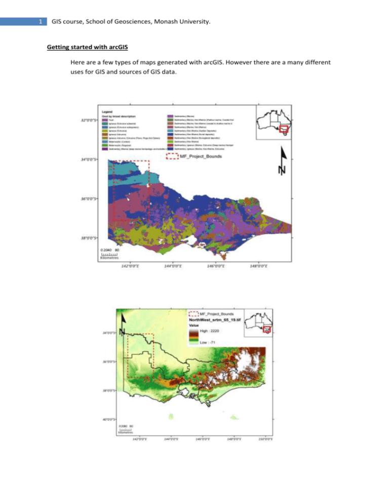
1 GIS course, School of Geosciences, Monash University. Getting started with arcGIS Here are a few types of maps generated with arcGIS. However there are a many different uses for GIS and sources of GIS data. 2 GIS course, School of Geosciences, Monash University. arcGIS interface 1. Layers window, adding layers toggle etc. Use the 4M scale to show broad scale stratigraphy. Zoom in to Moyston Fault, Stawell area. USE zoom tool, extents, pan etc. to show Ballarat 100k detail. Zoom out to show resolution issue. Highlight the importance of scale on choosing data to display. Use measure tool to show distance. Use effects toolbar for transparency and swiping. Use identify tool to observe the units. Bring up geophysical image and explain mapping techniques for interpet. Image editing (properties) to highlight geophysical images eg. 1vd on tmi. File directory importance e.g. external hard drives etc. TO DO Open a new .mxd and add shapefiles including: 1:4M geology 1:100k Ballarat geology Cities Roads Geophysical images grav and mag tmi and 1vd. Vic boundaries Mines sites SAVE work REVIEW work 1. View attributes (vic boundaries) in order to decide how to format the shapefile. Importance of saving shapefiles as a layer file. What the difference? Attributes can be sorted by zone name, and colour ramp, manual colour change etc. Label zones. Then using 100k sheet, sort by age and label with unit name to visualize multiple attributes. TO DO Experiment with attributes 2. Basic interpret. TO DO 3 GIS course, School of Geosciences, Monash University. Open ArcCatalog and produce new shapefiles e.g polylines, polygons etc. Creating new shapefiles (point, polylines, polygons) 1. Open ArcCatalog. The button (circled) should be found once ArcGIS has been opened. 2. Once in ArcCatalog, browse to the directory you wish the shapefile to be located in. Right-click in the right-hand pane and go to ‘New’ – ‘Shapefile’ (see left). Left-click on ‘Shapefile’ 3. Enter the name of the shapefile without using spaces. Use an underscore if you need to separate words (eg. ‘Andrew_Button_Prospects’) Choose the type of shapefile you need by left-clicking the down arrow at the right of the ‘Feature Type’ menu box. Click ‘Edit’ to select the coordinate system you are using. Click OK to create the shapefile 4 GIS course, School of Geosciences, Monash University. 4. If you need to add certain data to your shapefile, you can create fields to help you organise it. Right-click the shapefile and select ‘Properties’. Go to step 6 if this is not necessary. 5. Click on the ‘Fields’ tab at the top of the Shapefile Properties window. Some fields will already be added which GIS uses to organise itself, so it’s best to leave these alone. To add your own field, click within the next empty field (in this example the fourth line down) and type in the field name. Note that a cursor will not appear to indicate the field is ‘active’, so just start typing. Select the type of data you’ll be entering – usually this is text whether it is alpha or numeric. You can set the field length in the area under the list of fields, note that the values is the number of characters (including spaces) – not words. The default value of 50 is normally sufficient. Data can be added to these new fields in editing mode within Arc GIS. 6. To add the shapefile to your GIS map, either click and drag from ArcCatalog and drop into the required location in the Table of Contents within ArcGIS, or click on the ‘Add Layers’ button and browse to the files location (left) 7. Editing Use symbology to give the shapefiles a format and save as a layer file. Draw a series of interpreted boundaries, regions, faults etc. using the geophysical data and compare it to the map sheets provided. 5 GIS course, School of Geosciences, Monash University. 3. Georeferencing Different projection systems e.g. lat, long versus geographic. Which one and why? TO DO Georeference the 50k Ararat map map using AGD66 or AMG66 z54. 1. Open ArcCatalog and browse to the image you want to georeference. Before doing anything you need to set the projection of the image file. Right-click the image file and select properties. Find the ‘spatial reference’ entry and click ‘edit’ (left). Assign the coordinate system the image was created with (or, if unknown, that you are using in the GIS map) and click ‘ok’. Exit the image properties window by clicking ‘ok’. 2. Add the image file to the ArcGIS map with the ‘add data’ button. When the image appears in the Table of Contents, right-click and click ‘Zoom to layer’ to find it. Find the Georeferecing menu and open the ‘Link Table’ (top-left). This will display the entries you make as you go (bottom-left). Un-check the ‘Auto Adjust’ box if you don’t want the image to be moved as you add points. I prefer to keep it on as it helps to identify if the image is being georefenced correctly. 3. Once you have selected points on the image that have known co-ordinates you can start adding georeferencing points by right-clicking and choosing ‘Enter X and Y’. A Enter Coordinates box will appear and you can enter the coordinates manually. Make sure that you use either decimal degrees (left) or Easting – Northings format. Degrees-mins-secs won’t work! Three points is the minimum you need, though I find four tends to make a better job of it. Note that you can save your work as you go by clicking the ‘Save’ button. This can save time on especially tricky images 6 GIS course, School of Geosciences, Monash University. when you may have to start again. Just click ‘Load’ to restore the points if you need to re-add an image from scratch. 4. When the image has been georeferenced correctly, choose the ‘Update georeferencing’ option fro the georeferencing menu (top-left). This will ensure all you points have been updated. Then click ‘Rectify’ from the same menu to save the image and the georefencing you have done. This will prompt you to save the image. This is very important to remember! If you don’t rectify and you close the map down, you will loose all your hard work. When you save the image, you’ll need to add the rectified image to the GIS map. Remove the original image that you added in step 2 and the georeferencing points will be removed as well. Note some handy options are available from the georefencing menu. ‘Delete Control Points’ removes the points from the Link Table, though this can be done by selecting a point in the Link Table itself and clicking the ‘X’ (circled, bottom-left). ‘Reset transformation’ allows you to start the process again if things go awry. Digitise a part of the map using new shapefiles. Importance of workflow? Draw a series of polygons and clip one from the other to highlight efficiency of clipping. Use snapping and finish part tools to speed up drawing process. 4. Selecting attributes (structural point data file). TO DO Add this point data and edit format to display different symbols e.g. s0 s1. Symbol editing and symbol rotation. Display only 1 fabric generation (create query etc). 7 GIS course, School of Geosciences, Monash University. Selecting specific attributes from shapefiles 1. Open the attribute table of the shapefile you wish to use (rightclick the layer and select ‘Open attribute table’). Once the table has opened, click ‘Options’ at the bottom of the window and select ‘Select By Attributes…’ (at left) 2. Select the method you wish to use to select your attributes. ‘Create a new selection’ is used in most instances. Double-click the column name you wish to sort with (in the case to the left ‘Descrip’ is where the age of the rock unit depicted by the polygon is stored). Click the operator required (eg. ‘=’) and then enter the search keyword (eg. ‘HOLOCENE’ – at left). Please note that words require single quotation marks (‘HOLOCENE’) whereas numbers do not. If you do not use quote marks around words the search will fail, as will using quote marks around numbers. 3. If you get stuck click ‘Help’. This window contains some helpful hints and reminders that assist in entering the correct search syntax. 8 GIS course, School of Geosciences, Monash University. 4. To verify the search ‘expression’ has been entered correctly, click ‘Verify’. This will perform the search to verify that it will return a result, but won’t select the searched attributes. If the search has been entered correctly AND obtains a result you will receive the message to the top-left – this is good! You can then make your selection by clicking ‘Apply’. If the expression was entered correctly, but no results are returned the message at middle-left will appear. You may need to check upper versus lower case or spelling. Sometimes words can be mis-spelt or spelt differently. If everything was entered incorrectly then you receive the message at bottom-left. This means you have entered the expression incorrectly – it’s probably best to use the help option from step 3 to check what is wrong with it. 5. If all goes well with the search, the selected objects will be highlighted in the attribute table (left). If you wish you can close the Select by attribute window by clicking close. To view only the selected objects click ‘Selected’ at the bottom of the window (circled) 6. To create a new layer using only the selected attributes, right-click the layer in the Table of Contents and go to ‘Selection’ and click ‘Create layer from selected features’. 9 GIS course, School of Geosciences, Monash University. 7. A new layer will appear with the same name as that of the original layer, but with ‘selection’ added. It’s good to rename these layers to avoid confusion. 8. The result using the Holocene unit example can be seen at left. The right-hand image shows the new layer based on selecting only Holocene objects 5. Layout view allows the addition grids, legend, north arrow, scale etc for publication in different formats. Create a map (using either the dataset provided or from your field area) with description for grading. Lucid brevity to be rewarded. 50% participation, 50% output. GOOD LUCK with GIS.

