FOURIER SYNTHESIZER
advertisement
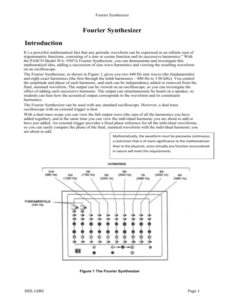
Fourier Synthesizer Fourier Synthesizer Introduction It’s a powerful mathematical fact that any periodic waveform can be expressed as an infinite sum of trigonometric functions, consisting of a sine or cosine function and its successive harmonics." With the PASCO Model WA- 9307A Fourier Synthesizer, you can demonstrate and investigate this mathematical idea, adding a succession of sine wave harmonics and viewing the resulting waveform on an oscilloscope. The Fourier Synthesizer, as shown in Figure 1, gives you two 440 Hz sine waves (the fundamentals) and eight exact harmonics (the first through the ninth harmonics—880 Hz to 3.96 kHz). You control the amplitude and phase of each harmonic, and each can be independency added or removed from the final, summed waveform. The output can be viewed on an oscilloscope, so you can investigate the effect of adding each successive harmonic. The output can simultaneously be heard on a speaker, so students can hear how the acoustical output corresponds to the waveform and its constituent harmonics. The Fourier Synthesizer can be used with any standard oscilloscope. However, a dual trace oscilloscope with an external trigger is best. With a dual trace scope you can view the full output wave (the sum of all the harmonics you have added together), and at the same time you can view the individual harmonic you are about to add or have just added. An external trigger provides a fixed phase reference for all the individual waveforms, so you can easily compare the phase of the final, summed waveform with the individual harmonic you are about to add. Mathematically, the waveform must be piecewise continuous, a restriction that is of more significance to the mathematician than to the physicist, since virtually any function encountered in nature will meet the requirements. Figure 1 The Fourier Synthesizer EED, LSBU Page 1 Equipment Set-up Connect the Fourier Synthesizer to your oscilloscope as shown in Figure 2. 1. Connect the ground of the oscilloscope to one of the ground jacks on the Synthesizer. 2. Connect the Synthesizers TRIGGER OUTPUT to the external trigger jack on the scope. (If you are using an oscilloscope with a recurrent sweep, connect the TRIGGER OUTPUT on the Synthesizer to the external sync jack on the scope.) 3. Connect the scope input to one of the 10 kΩ OUTPUT jacks on the Synthesizer. The 10 kΩ output jacks include one jack for each of the 10 channels and one jack at the bottom center of the Synthesizer that outputs the sum of all the harmonics that have been added together. If you are using a dual trace scope, connect Channel 1 to the summed output and use Channel 2 to view the individual harmonics as you add them into the waveform NOTE: If you are using PASCO’s WA-9305 Oscilloscope Connecting Cables, connect the BNC connectors to your oscilloscope inputs, connect the black banana plugs to the ground jacks on the Synthesizer, and connect the red banana plugs to the 10 kΩ outputs. 1. 2. If you are using an unshielded input cable, it should be separated as far as possible from the trigger cable to reduce AC interference from the trigger signal. If you want to hear the output, as well as see it, connect a speaker with an input impedance of 8Ω, between the two 8Ω OUTPUT jacks on the bottom right of the Synthesizer. 3. Figure 2 Equipment Setup Operation 1. Connect the Fourier Synthesizer to an oscilloscope as explained in the previous section. 2. Turn on the oscilloscope, and set the oscilloscope sensitivity to about 0.5 volts/cm. 3. Switch the power switch (bottom left hand comer of the Synthesizer) to ON. 4. The controls of the Synthesizer are arranged in ten columns. Each column of control knobs controls one of the ten individual waveforms. The purposes of the knobs are described in Figure 3, below. The controls for each waveform arc identical, except that the first two columns, the fundamental waveforms, have two additional switches. Unlike the higher harmonics, the fundamentals can be switched to obtain triangular or square waves at the fundamental frequency (440 Hz). To become familiar with the controls: a. Connect the input of the oscilloscope to the 10 kΩ output jack of the first fundamental, near the bottom of the leftmost column. If you are using a dual trace scope, connect the second input to the 10 kΩ output summing jack at the bottom center of the Synthesizer. b. Adjust the Amplitude control knob of the first fundamental until a trace appears on the oscilloscope. Phase knob. (If you are triggering the oscilloscope with the TRIGGER OUTPUT from the Synthesizer, you will see the trace on the oscilloscope shift to the right or left.) This knob gives you continuous control of the phase over a range of at least 90’. d. Try sliding the 0<=>900 switch and then the 0<=> 1800 switch and observe die signal on your oscilloscope. Using these switches, along with the variable control knob, lets you vary the phase of any individual waveform by a full 3600. e. Try sliding the two slide switches at the top of the column. These switches allow you to change the waveform from a sine wave to a square or triangular wave. f. Now slide the SUMMING AMPLIFIER slide switch to IN. The waveform is now passed through to the summing amplifier, and appears on the second trace of your dual trace scope. (If you are using a single trace scope, plug the oscilloscope input into the 10 kΩ OUTPUT jack of the summing amplifier to see the output of the summing amplifier.) g. Now try examining the signals from the remaining columns of the Synthesizer. Vary the amplitude and phase of these signals then slide the SUMMING AMPLIFIER switch for that column to IN to see what happens when you add that waveform to the summed output Figure 3 Synthesizer Controls IMPORTANT NOTES: 1. The summing amplifier produces a 1800 phase shift in each individual waveform. Therefore, when you switch an individual waveform into the summing amplifier, flip the 0↔1800 switch for that waveform in order to maintain the same phase relationship you have set between it and the summed output. 2. When experimenting, periodically hit the Synthesizer RESET button (lower right comer). Transients in the power line will occasionally affect the digital circuitry of the Synthesizer, and can alter the phase relationships of the waveforms. Pushing RESET will reset the digital circuitry. 3. The amplitude of the fundamentals (the two columns labelled 1) and the Second and Third harmonics (the columns labelled 2 and 3) can be varied up to 2 volts peak-to-peak. The amplitudes of the higher harmonics have a maximum of 1 volt peak-to-peak. This makes it easier to make the fine amplitude adjustments that are often necessary for the higher harmonic. Experiments HELPFUL TIPS 1. Before beginning an experiment, “zero” the Fourier Synthesizer a. Set all the phase switches to zero (the Variable Phase knob, and the 0↔90 and 0↔180 switches). b. Set all the summing amplifier switches to OUT. c. Press the RESET button 2. Set the summing amplifier switch for the first fundamental waveform to IN. Using your scope; examine the summed output of the Synthesizer. Determine an origin (00 point) on your scope, and adjust the horizontal position of the trace so the Synthesizer waveforms are either sines or cosines (whichever you prefer). Remember: 1. The summing amplifier produces a 1800 phase shift in each individual waveform when it is added to the summed output 2. When experimenting, periodically press the RESET button to be sure all the waveforms stay in phase. Experiment 1: Adding Sine Waves of the Same Frequency INTRODUCTION There are standard trigonometric identities that can be used to mathematically add sine waves and cosine waves. You can then graph the resulting waveform to determine exactly what the sum of the two waves would look like. Although a physicist needs to be able to use such mathematical tools, it’s also important to have an intuitive grasp of what is happening when trigonometric functions are added. PROCEDURE EED, LSBU Page 4 Note: This procedure assumes you are using an oscilloscope with an external trigger. 1. Hookup the Fourier Synthesizer to your oscilloscope as described in the SETUP section. Connect the oscilloscope input to the l0kΩ output connector of the summing amplifier. Trigger the oscilloscope from the TRIGGER output 2. Switch the first fundamental signal SUMMING AM-PLIFIER switch to the IN position. Make sure the second fundamental and all harmonics are switched OUT. Select the SINE wave output signal option. Adjust the AMPLITUDE control to a convenient value near maximum amplitude, (1V peak is usually convenient). Adjust the vertical scaling on the oscilloscope so that the peak of the sine wave is less than or equal to half of the maximum display on the scope, (0.5V/div is usually convenient). Adjust the 0↔900 and 00↔1800 switches and the VARIABLE PHASE control to display either a sine or cosine waveform. Switch the first fundamental signal OUT and the second fundamental signal IN. Adjust the controls for the second fundamental to produce a sine wave signal identical in amplitude and phase to the first fundamental signal. 3. Now switch the first fundamental signal IN to the summing Amplifier. Is the combined waveform a sine wave? How does its amplitude and phase compare with the amplitudes and phases of the two original sine waves? 4. Vary the amplitude of one of the fundamentals and examine the amplitude and phase of the combined wave. 5. Vary the phase of one of the fundamentals, first with the variable phase control, then with the 0↔900 and 00↔1800 switches. Examine the amplitude and phase of the combined wave. 6. What conditions produce a combined waveform with a maximum amplitude? A minimum amplitude? 7. Repeat the above procedure with two triangular waves and then two square waves. (Note: The VARIABLE PHASE control has no effect on the triangle and square wave outputs. The phase of these wave forms can only be shifted 900 or 1800 using the 0↔900 and 0↔1800 switches). Then try adding a square wave to a sine wave, a square wave to a triangular wave, and a sine wave to a triangular wave. In each case, first examine the constituent waves, then try to sketch what you believe the combined waveform will look like. Then add the two waves together to see how accurate your sketch was. Experiment 2: Adding Sine Waves of Different Frequencies INTRODUCTION Two sine waves of the same amplitude and phase can be added mathematically using the formula: sin(2𝜋𝑣1 ) + sin(2𝜋𝑣21 ) = 2cos𝜋(𝑣1 − 𝑣2 )𝑡sin𝜋(𝑣1 + 𝑣2 )𝑡 If v1 and v2 are greatly different, then the wave described by the right side of this equation is even more difficult to visualize than the wave described by the left side. However, if v1 and v2 are nearly the same, the cosine term will have a much lower frequency then the sine term. Then the wave can be visualized as a sine wave of frequency (v1 + v2)/2, with the amplitude of this sine wave varying slowly with a frequency of (v1 - v2)/2. If this EED, LSBU Page 5 were a sound wave, you would hear what is called beats, the relatively slow pulsing of the tone as the amplitude rises and falls. PROCEDURE NOTE: This procedure assumes you are using a dual trace scope with an external trigger. 1. Hookup the Fourier Synthesizer to your oscilloscope as described in the SETUP section. Connect one of the oscilloscope inputs to the 10 kΩ Output connector of the 9th harmonic. Connect the other oscilloscope input to the 10 kΩ Output connector of the summed waveform. 2. Switch the 8th harmonic into the summing amplifier. Make sure all the other waveforms arc switched out. Examine the 8th and 9th harmonics at the same time. Determine the frequency of each wave and record it. Adjust their amplitudes and phases to the same values. 3. Now add the two waves by switching the 9th harmonic into the summing amplifier (be sure to flip the 0↔180 switch at the same time to offset the 180° phase shift caused by the summing amplifier). Describe the resulting waveform. Do you see beats? If so, what is the frequency of the beats? What is the frequency of the modulated wave? 4. Describe what happens as you vary the amplitude or phase of either harmonic. 5. Repeat he above steps using different combinations of harmonics, such as the 7th and the 8th, the 7th and the 9th, the 1st and the 2nd, the 2nd and the 9th. Try any combinations that you think might be interesting. In each case, describe your results. Is the resulting waveform periodic? If so, what is the period? Do beats occur? 6. From your observations, what generalizations can you make about adding sine waves of different frequencies? Under what conditions do you expect beats? Experiment 3: Fourier Synthesis INTRODUCTION Joseph Fourier discovered that any periodic function can be expressed as an infinite sum, or series, of sine and cosine functions. In such an infinite series, each term is a harmonic of some fundamental frequency. That is to say, the frequency of each term is an integer times some constant frequency. The Fourier Series is one of many reasons why harmonic motion is so important in physics and technology. Using Fourier analysis, any periodic motion can be understood as a superposition of harmonic motions. Since harmonic motion is well understood, this offers a powerful approach to studying a large variety of phenomena. In this experiment, you will have a chance to see how several different waveforms can be built up ("synthesized") by adding sine or cosine waveforms. PROCEDURE 1. Hook up the Fourier Synthesizer to your oscilloscope as described in the SETUP section. EED, LSBU Page 6 2. Connect the oscilloscope input to the 10 kil Output connector of the summing amplifier. If you are using a dual trace scope, you can use the other trace to examine the harmonic waveforms before you add them in to the combined waveform. 3. Zero the Synthesizer. That is, set the phase of all the harmonics to zero. 4. Create a square wave as follows: a. Switch the fundamental into the summing amplifier (flip the SUMMING AMPLIFIER switch to IN). Adjust the amplitude as high as it will go and adjust the horizontal position of the trace so the wave looks like a cosine function. b. Switch out the fundamental and switch in the 3rd harmonic. Adjust its amplitude to 1/3 the amplitude of the fundamental. Shift its phase by 180* so that it looks like a minus cosine function. c. Switch out the 3rd harmonic and switch in the 5th harmonic. Adjust its amplitude to 1/5 that of the fundamental. The phase should be the same as the fundamental. d. Switch out the 5th harmonic and switch in the 7th harmonic. Adjust its amplitude to 1/7 the amplitude of the fundamental. Shift its phase by 180' so that it looks like a minus cosine function. e. Switch out the 7th harmonic and switch in the 9th harmonic. Adjust its amplitude to 1/9 that of the fundamental. The phase should be the same as the fundamental f. Now switch all the harmonics you have just adjusted into the summing amplifier. Observe how each harmonic adds to the square waveform. Of course, to get a perfect square wave, you would have to add an infinite number of harmonics, following this same pattern. NOTE: You can often improve your final waveform by making small adjustments Jo the phase angles (the Variable Phase controls are very sensitive and may not be perfectly zeroed when you start). Start over building the wave. Begin with the fundamental. Then add the 3rd harmonic and adjust its phase until the combined waveform is perfectly symmetrical. Add each successive harmonic, each time adjusting the phase until the waveform is perfectly symmetrical. The accuracy of the waveform also depends on how closely the amplitude of each harmonic fits the specifications given above. 5. You can build other waveforms using the table on the next page. The table lists the relative amplitude of each harmonic needed. The number in parentheses below the relative amplitude gives the phase shift of the harmonic relative to the phase of the TRIGGER output, (e.g., for the square wave, the amplitude of the third harmonic should be 33% of the amplitude of the fundamental and it should be shifted forward by 1800 with respect to the fundamental.) Waveform Harmonics 1* EED, LSBU 2 3 4 5 6 7 8 9 Page 7 Square 100 0 (0°) Triangular 100 100 0 (180°) 0 (0°) Sawtooth 33 11 33 0 (0°) 0 (0°) 50 20 4 14 0 (180°) 0 (0°) 2 (0°) 0 (0°) 25 20 17 14 11 1.2 (0°) 12.5 11 (see note below) (90°) (270°) (90°) (270°) (90°) (270°) (90°) (270°) (90°) Rectified 100 20 4.8 3.3 2.1 12 cosine (0°) (180°) (0°) (180°) (0°) (180°) (0°) (180°) (0°) Parabola 100 25 11 6.7 4 3 1.5 1.2 (0°) (0°) (0°) (0°) (0°) , (0°). (0°) (0°) (0°) 8.3 13 2 0.9 *Fundamental Waveform (440 Hz) NOTE: The sawtooth waveform must be constructed using sine (not cosine) waves. The 900 phase shift shown for the fundamental is intended to show this, since the 0<=>900 switch must be in the 900 position to produce a sine wave when the TRIGGER output is used as the time reference. The 2700 phase shift for even- numbered harmonics implies 1800 phase shift relative to the fundamental, and is obtained by switching the 0↔90 switch to the 900 position and the 0↔1800 switch to the 1800 position EED, LSBU Page 8
