IndexOfReflectionLab - joshuabryant
advertisement
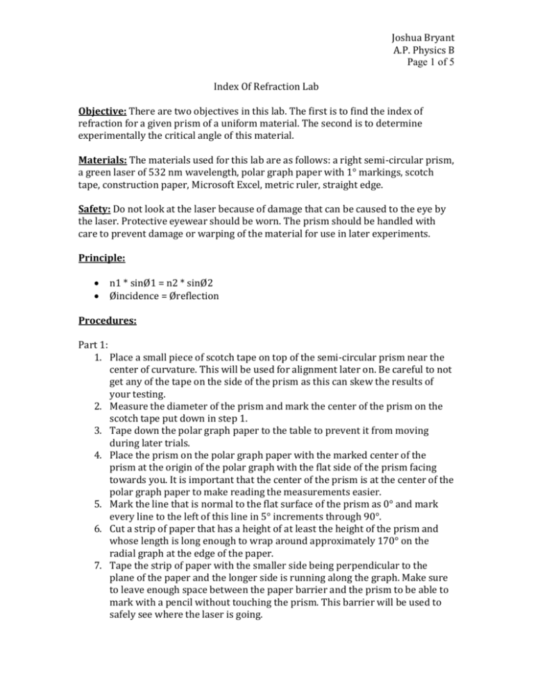
Joshua Bryant A.P. Physics B Page 1 of 5 Index Of Refraction Lab Objective: There are two objectives in this lab. The first is to find the index of refraction for a given prism of a uniform material. The second is to determine experimentally the critical angle of this material. Materials: The materials used for this lab are as follows: a right semi-circular prism, a green laser of 532 nm wavelength, polar graph paper with 1° markings, scotch tape, construction paper, Microsoft Excel, metric ruler, straight edge. Safety: Do not look at the laser because of damage that can be caused to the eye by the laser. Protective eyewear should be worn. The prism should be handled with care to prevent damage or warping of the material for use in later experiments. Principle: n1 * sinØ1 = n2 * sinØ2 Øincidence = Øreflection Procedures: Part 1: 1. Place a small piece of scotch tape on top of the semi-circular prism near the center of curvature. This will be used for alignment later on. Be careful to not get any of the tape on the side of the prism as this can skew the results of your testing. 2. Measure the diameter of the prism and mark the center of the prism on the scotch tape put down in step 1. 3. Tape down the polar graph paper to the table to prevent it from moving during later trials. 4. Place the prism on the polar graph paper with the marked center of the prism at the origin of the polar graph with the flat side of the prism facing towards you. It is important that the center of the prism is at the center of the polar graph paper to make reading the measurements easier. 5. Mark the line that is normal to the flat surface of the prism as 0° and mark every line to the left of this line in 5° increments through 90°. 6. Cut a strip of paper that has a height of at least the height of the prism and whose length is long enough to wrap around approximately 170° on the radial graph at the edge of the paper. 7. Tape the strip of paper with the smaller side being perpendicular to the plane of the paper and the longer side is running along the graph. Make sure to leave enough space between the paper barrier and the prism to be able to mark with a pencil without touching the prism. This barrier will be used to safely see where the laser is going. Joshua Bryant A.P. Physics B Page 2 of 5 8. Place the laser at the 0° mark and face it towards the center of the prism. 9. Turn on the laser and mark down on the paper barrier along with at least two spots on the graph paper at least two spots where the laser passes through after passing through the prism. 10. Turn off the laser and connect the marks made and extend the line. Mark down the nearest degree marking to the line made by the laser and record the value of the angle made by the laser and the normal. 11. Move the laser 5° to the left to the next marking, face the laser to point to the center of the prism. 12. Repeat steps 9 through 11 for every 5° mark through 90°. Part2: 1. Continuing from Part 1, turn the prism around 180° so that the curved side is now facing you and the flat side is facing away from you. 2. Re-align the prism so that the center of the prism is again at the center of the graph and the normal is still running through the center of the arc. This is important to guarantee that the laser will be normal to the surface of the prism through this section making it easier to record the angle of reflection. 3. Place the laser at the 0° mark and point it towards the center of the prism and turn on the laser. 4. Begin to slowly move the laser to the left while keeping the laser pointed at the center of the prism throughout the movement. Notice that there will be two dots that appear on the paper barrier, one on the other side of the prism that is the light passing through the prism and one dot that is on the same side of the prism as the laser, which is the reflected light. 5. Keep moving until the dot on the side of the prism opposite the laser disappears. At this point, stop moving the laser and record the spot on the paper barrier and two spots on the graph paper. Draw a line through the points and mark down the nearest angle to this line from the normal. This is the angle of reflection off the flat surface of the prism and is equal to the angle of incidence of the laser with the flat surface. Joshua Bryant A.P. Physics B Page 3 of 5 Data: Part 1: Ø1 0 5 10 15 20 25 30 35 40 45 50 55 60 65 70 75 80 85 Ø2 0 3 7 10 13 16 19 22 25 29 32 35 37 39 41 43 44 45 Part 2: Angle of Reflection: 42° sinØ1 0 0.09 0.17 0.26 0.34 0.42 0.50 0.57 0.64 0.71 0.77 0.82 0.87 0.91 0.94 0.97 0.98 1.00 sinØ2 0 0.05 0.12 0.17 0.22 0.28 0.33 0.37 0.42 0.48 0.53 0.57 0.60 0.63 0.66 0.68 0.69 0.71 Joshua Bryant A.P. Physics B Page 4 of 5 Conclusion/Results: Joshua Bryant A.P. Physics B Page 5 of 5 By plotting the values obtained as sine of the input angle over the sin of the second angle and drawing the line of best fit, we can determine the index of refraction of the semi-circular prism as being the slope of the line, 1.4428 in this case for light of 532 nm wavelength. Part 2: Because the angle of reflection was 42° at the point where the light from the laser on the opposite side of the prism disappeared, the angle of incidence of the laser with the flat surface was 42° from the normal making 42° the critical angle of the material.
