DeMorgan's Theorems Activity: Digital Electronics Simplification
advertisement
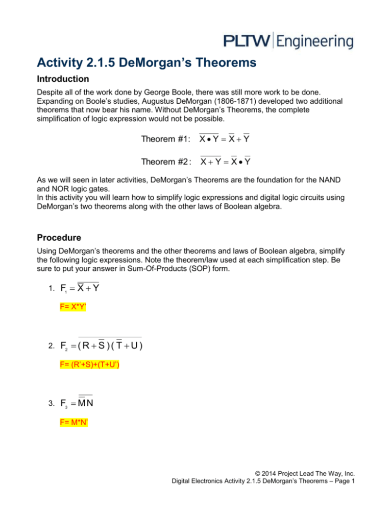
Activity 2.1.5 DeMorgan’s Theorems Introduction Despite all of the work done by George Boole, there was still more work to be done. Expanding on Boole’s studies, Augustus DeMorgan (1806-1871) developed two additional theorems that now bear his name. Without DeMorgan’s Theorems, the complete simplification of logic expression would not be possible. Theorem #1: XY X Y Theorem #2 : X Y XY As we will seen in later activities, DeMorgan’s Theorems are the foundation for the NAND and NOR logic gates. In this activity you will learn how to simplify logic expressions and digital logic circuits using DeMorgan’s two theorems along with the other laws of Boolean algebra. Procedure Using DeMorgan’s theorems and the other theorems and laws of Boolean algebra, simplify the following logic expressions. Note the theorem/law used at each simplification step. Be sure to put your answer in Sum-Of-Products (SOP) form. 1. F1 X Y F= X*Y’ 2. F2 ( R S ) ( T U ) F= (R’+S)+(T+U’) 3. F3 M N F= M*N’ © 2014 Project Lead The Way, Inc. Digital Electronics Activity 2.1.5 DeMorgan’s Theorems – Page 1 4. F4 W X ( Y Z ) F= WX’+Y+Z’ 5. F5 P Q R P Q R F= (P’+Q+R’)(P+Q’+R) 6. F6 W X Y Z F= W+X’+Y’+Z Let’s see how we would utilize DeMorgan’s theorems to simplify a digital logic circuit. 7. Write the UN-SIMPLIFIED logic expression for the output Do-Nothing in the logic circuit shown below. F=(X’+Y”)(Y’Z’”)+(Y’+X”) The output is call Do-Nothing because that is exactly what the circuit does, nothing; yet it’s a good example for learning about DeMorgan’s theorems. 8. Using DeMorgan’s theorems and the other theorems and laws of Boolean algebra, simplify the logic expression Do Nothing. Be sure to put your answer in Sum-OfProducts (SOP) form. F=X’+X’YZ’+Y’Z © 2014 Project Lead The Way, Inc. Digital Electronics Activity 2.1.5 DeMorgan’s Theorems – Page 2 9. In the space provided, draw an AOI circuit that implements the simplified logic expression Do Nothing. For this implementation you may assume that AND & OR gates are available with any number of inputs. VCC Do_Nothing 5V 2.5 V U1 X U5 NOT Key = Space AND2 Y U2 U4 AND2 U6 NOT U8 OR2 OR2 U7 Key = Space U3 Z AND3 NOT GND Key = Space Do Nothing – I 10. Re-implement the circuit assuming that only 2-input AND gates (74LS08), 2-input OR gates (74LS32), and inverters (74LS04) are available. Draw this circuit in the space provided. VCC 5V X_ Key = Space Y_ U9 Do__Nothing U13NOT U12 AND2 U10 AND2 2.5 V U14 U15 NOT U17 U11 AND2 Key = Space Z_ NOT GND OR2 U16 OR2 AND2 Key = Space Do Nothing – II © 2014 Project Lead The Way, Inc. Digital Electronics Activity 2.1.5 DeMorgan’s Theorems – Page 3 Conclusion 1. Draw the gate equivalent for DeMorgan’s two theorems. 2. Theorem #1: XY X Y U15 OR2 Theorem #2 : X Y XY U16 AND2 3. How would you prove that the original Do Nothing circuit and the simplified version are equivalent? By making a truth table and comparing them. 4. If each GATE cost 5¢ and you made 100,000 of the unsimplified units, how much of the company’s money did you waste on the unsimplified Do-Nothing project? 25,000.oo © 2014 Project Lead The Way, Inc. Digital Electronics Activity 2.1.5 DeMorgan’s Theorems – Page 4
