Design of Solar Power Generation System using Nine level Inverter
advertisement

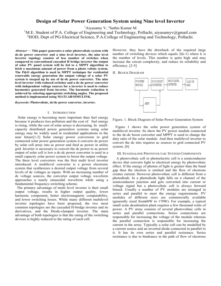
Design of Solar Power Generation System using Nine level Inverter 1 Aiyasamy V, 2Sathis Kumar M 1 M.E. Student of P.A. College of Engineering and Technology, Pollachi, aiyasamyv@gmail.com 2 HOD, Dept of PG-Electrical Science, P.A.College of Engineering and Technology, Pollachi. Abstract— This paper generates a solar photovoltaic system with dc-dc power converter and a nine level inverter, the nine level inverter topology consists of less number of switches when compared to conventional cascaded H bridge inverter the output of solar PV panel system will be fed to a MPPT algorithm to fetch a maximum amount of power from a photo voltaic system. The P&O algorithm is used in MPPT technique for residential renewable energy generation the output voltage of a solar PV system is steeped up by use of dc-dc power converter. The nine level inverter with reduced switches and a dc-dc power converter with independent voltage sources for a inverter is used to reduce harmonics generated from inverter. The harmonic reduction is achieved by selecting appropriate switching angles. The proposed method is implemented using MATLAB/SIMULINK. However, they have the drawback of the required large number of switching devices which equals 2(k-1) where k is the number of levels. This number is quite high and may increase the circuit complexity, and reduce its reliability and efficiency. [2-5] II. BLOCK DIAGRAM Keywords: Photovoltaic, dc/dc power converter, inverter. I. INTRODUCTION Solar energy is becoming more important than fuel energy because it produces less pollution and the cost of fuel energy is rising, while the cost of solar arrays is decreasing. In smallcapacity distributed power generation systems using solar energy may be widely used in residential applications in the near future[1-2] Solar energy power conversion in grid connected solar power generation system it converts dc power by solar cell array into ac power and feed ac power in utility grid .Inverter is necessary to convert the dc power to ac power output of solar cell is low a dc-dc power converter is used in a small capacity solar power system to boost the output voltage. The three level converters was the first multi level inverter introduced. A multilevel converter is a power electronic system that synthesizes a desired output voltage from several levels of dc voltages as inputs. With an increasing number of dc voltage sources, the converter output voltage waveform approaches a nearly sinusoidal waveform while using a fundamental frequency-switching scheme. The primary advantage of multi level inverter is their small output voltage, results in higher output quality, lower harmonic component, better electromagnetic computability, and lower switching losses. While many different multilevel inverter topologies have been proposed, the two most common topologies are the cascaded H-bridge inverter and its derivatives, and the Diode-clamped inverter. The main advantage of both topologies is that the rating of the switching devices is highly reduced to the rating of each cell. Figure. 1. Block Diagram of Solar Power Generation System Figure 1 shows the solar power generation system of multilevel inverter. Its show the PV power module connected to the dc-dc boost converter and MPPT is used to change the duty ratio of the solar module. And then multilevel inverter to convert the dc into requires ac sources to grid connected PV system. [8] III. STANDALONE PHOTOVOLTAIC SYSTEM COMPONENTS A photovoltaic cell or photoelectric cell is a semiconductor device that converts light to electrical energy by photovoltaic effect. If the energy of photon of light is greater than the band gap then the electron is emitted and the flow of electrons creates current. However photovoltaic cell is different from a photodiode. In a photodiode light falls on n channel of the semiconductor junction and gets converted into current or voltage signal but a photovoltaic cell is always forward biased. Usually a number of PV modules are arranged in series and parallel to meet the energy requirements. PV modules of different sizes are commercially available (generally sized from60W to 170W). For example, a typical small scale desalination plant requires a few thousand watts of power. A PV array consists of several photovoltaic cells in series and parallel connections. Series connections are responsible for increasing the voltage of the module whereas the parallel connection is responsible for increasing the current in the array. Typically a solar cell can be modelled by a current source and an inverted diode connected in parallel to it. It has its own series and parallel resistance. Series resistance is due to hindrance in the path of flow of electrons from n to p junction and parallel resistance is due to the leakage current.[3-5] Figure.3. Circuit Diagram of Boost Converter Figure.2. Single Diode Model of a PV Cell. In this model consider a current source (I) along with a diode and series resistance (Rs). The shunt resistance (RSH) in parallel is very high, has a negligible effect and can be neglected. The output current from the photovoltaic array is 𝐼 = 𝐼𝑠𝑐 – 𝐼𝑑 𝑞𝑉𝑑 𝐼𝑑 = 𝐼𝑜 (𝑒 𝑘𝑇 − 1) (1) (2) Where Io is the reverse saturation current of the diode, q is the electron charge, Vd is the voltage across the diode, k is Boltzmann constant (1.38 * 10-19 J/K) and T is the junction temperature in Kelvin (K). Figure .4. Mode 1 Operation of Boost Converter When the switch is closed the inductor gets charged through the battery and stores the energy. In this mode inductor current rises (exponentially) but for simplicity we assume that the charging and the discharging of the inductor are linear. The diode blocks the current flowing and so the load current remains constant which is being supplied due to the discharging of the capacitor. From equations. Simplify 𝐼 = 𝐼𝑠𝑐 – 𝐼𝑜 (𝑒 𝑞𝑉𝑑 𝑘𝑇 − 1) (3) Using suitable approximations, 𝐼 = 𝐼𝑠𝑐 – 𝐼𝑜 (𝑒 𝑞((𝑉 + 𝐼𝑅𝑠)/𝑛𝑘𝑇) − 1) (4) Where, I is the photovoltaic cell current, V is the PV cell voltage, T is the temperature (in Kelvin) and n is the diode ideality factor In order to model the solar panel accurately using two diode model but in our project our scope of study is limited to the single diode model.[5] Also, the shunt resistance is very high and can be neglected during the course of our study. Figure.5. Mode 2 Operation of Boost Converter In mode 2 the switch is open and so the diode becomes short circuited. The energy stored in the inductor gets discharged through opposite polarities which charge the capacitor. The load current remains constant throughout the operation. Output Current and Voltage Waveforms for A Boost Converter. [5][7], [10-12] IV. BOOST CONVERTER The maximum power point tracking is basically a load matching Problem. In order to change the input resistance of the panel to match the load resistance (by Varying the duty cycle), a DC to DC converter is required. It has been studied that the efficiency of the DC to DC converter is maximum for a buck converter, then for a buck-boost converter and minimum for a boost converter but as we intend to use our system either for tying to a grid or for a water pumping system which requires 230 Vat the output end, so we use a boost converter. Figure.6.Output Current and Voltage Waveforms for A Boost Converter The simulation of solar PV cell with boost converter is shown in figure VI. MULTILEVEL INVERTER The multilevel inverters are used as voltage source inverters (VSIs) in the static synchronous compensator (STATCOM), a reactive power compensating device used for voltage regulation in power systems.[9] There are mainly three types of multilevel inverters, Diode- Clamped, Flying Capacitor and Cascade Multilevel Inverter (CMLI). Among these three, CMLI has a modular structure and requires least number of components as compared to other two topologies, and as a result, it is widely used for many applications in electrical engineering. [12-15]To produce multilevel output ac voltage using different levels of dc inputs, the semiconductor devices must be switched on and off in such a way that the fundamental voltage is obtained as desired along with the elimination of certain number of higher order harmonics in order to have least harmonic distortion in the ac output voltage.[16-17] The proposed nine level inverter is simulated using MAT LAB. Figure.7.Simulation Diagram of Solar System and Boost Converter Figure.9.Simulation Diagram of nine level inverter The output voltage waveform of solar PV cell and boost converter are shown in Figure.8. Solar Systems and Boost Converter Simulation Result The output voltage waveform of nine level inverter is shown in the figure Figure.10.Output Voltage Wave Form of Nine Level Inverter TABLE 1 Comparison Of Different Multilevel Inverter Switches Number of Switches Inverter Type Cascaded H Bridge Proposed method % Switching Reduction % Harmonic Reduction 5level 8 7level 12 9level 16 11level 20 6 8 10 12 25 % 33.3% 37.5% 40% 30.26 25.14 20.18 18.24 VII. Conclusion This paper proposes a solar power generation system to convert the dc energy generated by a solar cell array into ac energy that is fed into the utility. The proposed solar power generation system is composed of a dc–dc power converter and a nine level inverter. The nine-level inverter contains less power electronic switches, which simplifies the circuit configuration. This reduces the switching power loss and improvesthepowerefficiency. Experimental results show that the proposed solar power generation system generates a ninelevel output voltage and outputs a sinusoidal current that is in phase with the utility voltage, yielding a power factor of unity. In addition, the proposed solar power generation system can effectively trace the maximum power of solar cell array. REFERENCES [1] R. A. Mastromauro, M. Liserre, and A. Dell’Aquila, “Control issues in single-stage photovoltaic systems: MPPT, current and voltage control,”IEEE Trans. Ind. Informat., vol. 8, no. 2, pp. 241–254, May. 2012. [2] J. T. Bialasiewicz, “Renewable energy systems with photovoltaic powergenerators: Operation and modeling,” IEEE Trans. Ind. Electron., vol. 55,no. 7, pp. 2752–2758, Jul. 2008. [3] N. A. Rahim, K. Chaniago, and J. Selvaraj, “Single-phase seven-levelgridconnected inverter for photovoltaic system,” IEEE Trans. Ind. Electr.,vol. 58, no. 6, pp. 2435–2443, Jun. 2011. [4] J. M. Shen, H. L. Jou, and J. C. Wu, “Novel transformer-less gridconnectedpower converter with negative grounding for photovoltaic generationsystem,” IEEE Tra ns. Power Electron., vol. 27, no. 3, pp. 1304– 1313,Mar. 2013. [5] Z. Zhao, M. Xu,Q. Chen, J. S. Jason Lai, andY. H. Cho, “Derivation, analysis,and implementation of a boost–buck converter-based highefficiencypv inverter,” IEEE Trans. Power Electron., vol. 27, no. 3, pp. 1304– 1313,Mar. 2012. [6] P. Lezana, J. Rodr´ıguez, and D. A. Oyarz´un, “Cascaded multilevel inverterwith regeneration capability and reduced number of switches,” IEEETrans. Ind. Electron., vol. 55, no. 3, pp. 1059–1066, Mar. 2008. [7] T. A. Meynard, H. Foch, F. Forest, C. Turpin, F. Richardeau, L. Delmas,G. Gateau, and E. Lefeuvre, “Multicell converters: Derived topologies,”IEEE Trans. Ind. Electron., vol. 49, no. 5, pp. 978–987, Oct.2002. [8] V. Salas and E. Olias, “Maximum power point tracking in the PV gridconnectinverters of 5 kW,” in Proc. 34th IEEE Photovoltaic Spec. Conf.,2009, pp. 193–196. [9] J.-S. Lai and F. Z. Peng, “Multilevel converters—A new breed of powerconverters,” IEEE Trans. Ind. Appl., vol. 32, no. 3, pp. 509–517, May/Jun.1996. [10] J. D. Barros, J. F. A. Silva, and E. G. A Jesus, “Fast-predictive optimalcontrol of NPC multilevel converters,” IEEE Trans. Ind. Electron., vol. 60,no. 2, pp. 619–627, Feb. 2013. [11] M. A. Perez, J. Rodriguez, E. J. Fuentes, and F. Kammerer, “Predictivecontrol of ac–ac modular multilevel converters,” IEEE Trans. Ind.Electron., vol. 59, no. 7, pp. 2832–2839, Jul. 2012. [12] J. Chavarria, D. Biel, F. Guinjoan, C. Meza, and J. J. Negroni, “Energybalancecontrol of PV cascaded multilevel grid-connected inverters underlevel-shifted and phase-shifted PWMs,” IEEE Trans. Ind. Electron.,vol. 60, no. 1, pp. 98–111, Jan. 2013. [13] A. J.Watson, P.W. Wheeler, and J. C. Clare, “A complete harmonic eliminationapproach to DC link voltage- balancing for cascaded multilevelrectifier,” IEEE Trans. Ind. Electron., vol. 54, no. 6, pp. 2946– 2953, Dec.2007 [14] S. Sirisukprasert, A. Q. Huang, and J. S. Lai, “Modeling, analysis and controlof cascaded-multilevel converter-based STATCOM,” in Proc. IEEEPower Eng. Soc., 2003, pp. 2561–2568. [15] T. Esram and P. L. Chapman, “Comparison of photovoltaic array maximumpower point tracking techniques,” IEEE Trans. Energy Convers.,vol. 22, no. 2, pp. 439–449, Jun. 2007. [16] D. Floricau, E. Floricau, and G. Gateau, “New multilevel converters withcoupled inductors: Properties and control,” IEEE Trans. Ind. Electron.,vol. 58, no. 12, pp. 5344–5351, Dec. 2011. [17] H. Patel and V. Agarwal, “MPPT scheme for a PV-fed single-phase singlestagegrid-connected inverter operating in CCM with only one currentsensor,” IEEE Trans. Energy Convers., vol. 24, no. 1, pp. 256–263, Mar.2009.


