External photoelectric effect and Planck's constant –
wavelength selection with interference filters
TEP
Related Topics
Photon energy, photon absorption, external photo effect, work function, photocell, interference filter, quantum theory, Planck’s constant
Principle
The photoelectric effect is one key experiment in the development of modern physics. White light from a filament lamp
is filtered by an interference filter and illuminates a photocell. The maximum energy of the ejected electrons depends
only on the frequency of the incident light, and is independent of its intensity. This law appears to be in contradiction
with the electromagnetic wave theory of the light, but it becomes understandable in the frame of the corpuscular theory of light. The stopping voltage U0 at different light frequencies is determined by the I/U characteristics of the photocell and plotted over the corresponding light frequency f . Planck’s quantum of action is then determined from this
graph.
Equipment
1
1
1
1
1
1
2
1
Photocell with housing
Interference filters, set of 3
Interference filters, set of 2
Experimental lamp 5
Power supply 0…12 V DC / 6 V, 12 V AC
Universal measuring amplifier
Digital multimeter, 3 1/2 digits
Variable resistor, 100 Ohm, 1,8 A
06779-00
08461-00
08463-00
11601-00
13505-93
13626-93
07122-00
06114-02
4
3
1
2
1
1
Connecting cable, 4 mm plug, 32 A, red, 50 cm
Connecting cable, 4 mm plug, 32 A, blue, 50 cm
Connecting cable, 4 mm plug, 32 A, yellow, 50 cm
Connecting cable, 4 mm plug, 32 A, black, 50 cm
Connecting cable, 4 mm plug, 32 A, blue, 100 cm
TESS expert CD-ROM Laboratory Experiments
07361-01
07361-04
07361-02
07361-05
07363-04
16502-42
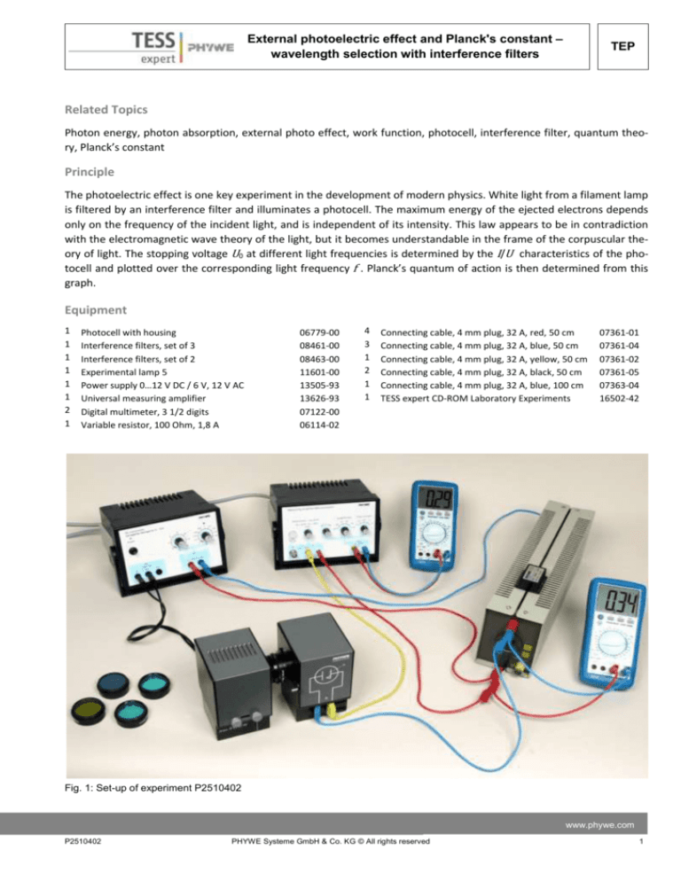
Fig. 1: Set-up of experiment P2510402
www.phywe.com
P2510402
PHYWE Systeme GmbH & Co. KG © All rights reserved
1
TEP
External photoelectric effect and Planck's constant – wavelength selection with interference filters
Tasks
1. Experimentally determine the stopping voltage U0 for
different light frequencies and intensities and plot it
over light frequency f.
2. Calculate Planck’s constant from the dependence of
the stopping voltage U0 on the light frequency f.
-
Set the power supply voltage on the potentiometer to
3 V, current to 1 A.
-
Put the photocell directly in front of the lamp, use the
round opening of the slider
-
The interference filters are fitted one after the other
to the light entrance of the photo-cell.
-
Observe the amplifier output which is proportional to
photo current in dependence on photocell bias voltage
-
Measure the bias voltage for zero current for different
frequencies
Set-up and Procedure
The experiment for the demonstration of the photoelectric effect is formed by: a photoelectric cell, the cathode
of which is irradiated with a light beam characterized by
the frequency f; a potentiometer allowing to apply a voltage U to the cell (positive or negative with respect to the
cathode); a voltmeter to measure this voltage; a microampere meter to measure the photoelectric current.
- The experimental set-up is as shown in Fig. 1.
-
Do the electrical connections as in Fig. 2
-
Set the measuring amplifier to low drift mode, amplification 104 and time constant 0.3 s
-
Check zeroing of universal amplifier – with no connection on the input set the amplifier output voltage to
zero with the zeroing control
Fig. 2:
2
Remarks on operation:
The measuring amplifier input has a resistance of 10,000
Ohm. If the amplifier is set to amplification 104, then one
volt at the amplifier output corresponds to 0.0001 V at
the input and thus to a current of 10 nA.
The time constant is set to avoid errors due to mains hum
influence.
Theory and evaluation
The external photoelectric effect was first described in
1886 by Heinrich Hertz. It soon became clear that this ef-
Electrical connections for the experiment
PHYWE Systeme GmbH & Co. KG © All rights reserved
P2510402
External photoelectric effect and Planck's constant –
wavelength selection with interference filters
fect shows certain characteristics that cannot be explained by the classical wave theory of light. For example,
when the intensity of the light shining on a metal becomes more intense, the classical wave theory would expect that the electrons liberated from the metal would
absorb more energy. However, experiments showed that
the maximum possible energy of the ejected electrons
depends only on the frequency of the incident light and is
independent of its intensity.
The theoretical explanation was given by Einstein in 1905.
He suggested that light could be considered to behave
like particles in some respect, moving with a constant velocity (the speed of light in vacuum) and possessing the
energy E = hf. Einstein's explanation of the photoelectric
effect, demonstrating the particle-like light behavior of
photons, contributed to the development of quantum
theory. Thus, the external photoelectric effect is one of
the key experiments in the development of modern physics and Einstein obtained the Nobel Prize in Physics “for
his discovery of the law of the photoelectric effect“.
termined using the stopping electric field method: A negative bias with respect to the cathode is applied on the
photoelectric cell anode. This decelerates the electrons
and thus decreases the photoelectric current intensity I
since not all electrons have maximum energy but they
have an energy distribution. The value of the bias where
no electron reaches the anode and I becomes zero is
called stopping voltage and is quoted U0.
Plotting I over the applied bias voltage Ubias reveals the
dependence of U0 on the wavelength λ of the incident
light and lack of dependence on light intensity, see Fig. 3.
The light intensity determines the photo current strength.
Table 1: Results
λ/nm
U0/V
f /1012 Hz
366
-1,50
820
405
-1,20
741
436
-1,00
688
546
-0,50
550
578
-0,40
520
Task 1: Determine the stopping voltage U0 experimentally
for different light frequencies and intensities and plot it
over the light frequency f.
Inside the photo-cell, a cathode with special low-work
function coating is situated together with a metal anode
in a vacuum tube. If a photon of frequency f strikes the
cathode, then an electron can be liberated from the cathode material (external photoelectric effect) if the photon
is sufficiently energetic.
If the emitted electrons reach the anode, they are absorbed by it due to the anode work function and the result is a photo current.
TEP
Task 2: Calculate Planck’s constant from the dependence
of the stopping voltage on the light frequency.
Electrons can only reach the anode if their kinetic energy
Wkin is greater than the energy they lose running counter
to the electric field set up by the bias voltage Ubias plus
the unknown electric field due to the contact voltage UAC
between the anode and cathode which has the same direction as the bias voltage, see Fig 3.
The photoelectric effect is an interaction of a photon with
an electron. In this reaction momentum and energy are
conserved, the electron absorbs the photon and has after
the reaction the full photon energy h f . If the energy of
the photon h f is greater than the extraction work WC
(cathode work function), the electron can after the reaction leave the substance with a maximum kinetic energy
Wkin = h f – WC. This is called external photoelectric effect
and described by:
hf
= WC + Wkin (Einstein’s equation ) (1)
The kinetic energy Wkin for the emitted electrons is de-
Fig. 3: Energy diagram for electrons in a photocell illuminated
with λ = 436 nm/f =688 THz and bias U0 = 1 V
www.phywe.com
P2510402
PHYWE Systeme GmbH & Co. KG © All rights reserved
3
TEP
External photoelectric effect and Planck's constant – wavelength selection with interference filters
A)
Fig. 3:
B)
The photoelectric current intensity I as a function of the bias voltage: A) at different frequencies of the irradiated light,
B) at different intensities (constant wavelength: 436 nm).
As the contact voltage is in the same order of magnitude
as the bias voltage, we cannot neglect it. Therefore, it is
not possible to determine the absolute kinetic energy of
the electrons. Nevertheless, the Planck’s constant can be
calculated from the dependence of the stopping voltage
on the light frequency, due to the following considerations:
At the stopping voltage U0, the kinetic energy Wkin of the
electron equals the energy lost in the electric field eU (U
including the stopping voltage U0 and the contact voltage
UAC):
e (U0 + UAC) = Wkin
4
(2)
The contact voltage is calculated from the electrochemical potentials of anode UA and cathode UC and multiplication of both with electron charge e = 1.602·10-19 As gives
their corresponding work functions WA and WC equation
(2) is equivalent to
eU0 + WA – WC = Wkin
(3)
To calculate Planck’s constant h using the photoelectric
effect, we compare (2) with Einstein equation (1):
Wkin = eU0 + WA – WC = h f – WC
PHYWE Systeme GmbH & Co. KG © All rights reserved
(3)
P2510402
External photoelectric effect and Planck's constant –
wavelength selection with interference filters
Accordingly, the cathode work function does not appear
in the formula for the stopping voltage and (3) can be
written as the following linear function
eU0
U0
= h f – WA
=
ℎ
𝑒
or
f – UA
(4)
As UA is a constant, a linear relationship exists between
the stopping voltage U0 and the light frequency f. The
slope of the linear function gives Planck's constant h. The
light frequency f can be calculated from the wavelength λ
of the interference filters by f = c / λ with speed of light
c = 299 792 458 m/s.
The measured slope is:
0,00366
𝑉
1012
1
𝑠
Multiplication with e gives: h = 5,59 . 10-34 Js
The calculated value may deviate ± 20 % from the literature value: h = 6.62 · 10-34 Js.
Notes
The cathode work function does not appear in the formula for the stopping voltage. This is due to the fact that the
electrons come from Fermi-level in the cathode and then
have to reach the anode surface and thus already have
TEP
been able to pass the cathode surface.
The cathode work function on the other hand determines
whether the photon energy is sufficient to liberate an
electron from the cathode. Historically, this photoeffect
threshold wavelength was also important for the discovery of this effect and only later was understood when the
electron energy spectrum of the liberated electrons was
systematically examined in dependence on light frequency and intensity.
Determining the stopping voltage U0 you will find curves
having only a small slope when crossing the x-axis (zero
point). An exact determination of the stopping voltage is
therefore complicated.
There is a negative current for higher bias voltages. This
current is due to the photo current from anode to cathode. Also from the anode electrons can be liberated. The
number of electrons there also depends on light frequency and in a different way than for the cathode. It can be
assumed, that the intensity and wavelength sensitivity of
the reverse photo electron current anode to cathode is
different from the one of the larger cathode to anode
electron current. So the zero point shift per light intensity
due to this effect is different for different wavelengths
making the zero point of the U/I characteristic curve of
the photocell a not very reliable measure.
The overall reverse current can nevertheless be regarded
as small because of the far lower work function of the
cathode compared to the anode. This justifies to neglect
this effect.
Else the zero point shift in dependence on intensity would
Fig. 3:
Stopping voltage U0 as a function o the frequency of the irradiated light.
www.phywe.com
P2510402
PHYWE Systeme GmbH & Co. KG © All rights reserved
5
TEP
External photoelectric effect and Planck's constant – wavelength selection with interference filters
have to be measured for each wavelength and would
have to be taken into account trying to achieve a normalization with respect to intensity.
Since effects of the electron energy distribution are also
present, the gain in precision by this procedure will not
be so great as to generally recommend it. Both the work
function for the electrons to leave the substance and the
electron energy before the reaction with the photon have
no sharp extrema so that the overall achievable precision
of this method is limited.
For a precise measurement of Planck's constant X-ray
measurements are more suitable, but the photoelectric
effect experiment has its justification by its great historic
relevance.
6
PHYWE Systeme GmbH & Co. KG © All rights reserved
P2510402

