Low Energy High Power Side Coupled Linac Optimization
advertisement

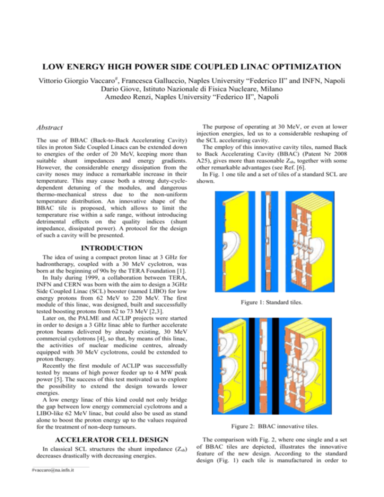
LOW ENERGY HIGH POWER SIDE COUPLED LINAC OPTIMIZATION Vittorio Giorgio Vaccaro#, Francesca Galluccio, Naples University “Federico II” and INFN, Napoli Dario Giove, Istituto Nazionale di Fisica Nucleare, Milano Amedeo Renzi, Naples University “Federico II”, Napoli Abstract The use of BBAC (Back-to-Back Accelerating Cavity) tiles in proton Side Coupled Linacs can be extended down to energies of the order of 20 MeV, keeping more than suitable shunt impedances and energy gradients. However, the considerable energy dissipation from the cavity noses may induce a remarkable increase in their temperature. This may cause both a strong duty-cycledependent detuning of the modules, and dangerous thermo-mechanical stress due to the non-uniform temperature distribution. An innovative shape of the BBAC tile is proposed, which allows to limit the temperature rise within a safe range, without introducing detrimental effects on the quality indices (shunt impedance, dissipated power). A protocol for the design of such a cavity will be presented. The purpose of operating at 30 MeV, or even at lower injection energies, led us to a considerable reshaping of the SCL accelerating cavity. The employ of this innovative cavity tiles, named Back to Back Accelerating Cavity (BBAC) (Patent Nr 2008 A25), gives more than reasonable Zsh, together with some other remarkable advantages (see Ref. [6]. In Fig. 1 one tile and a set of tiles of a standard SCL are shown. INTRODUCTION The idea of using a compact proton linac at 3 GHz for hadrontherapy, coupled with a 30 MeV cyclotron, was born at the beginning of 90s by the TERA Foundation [1]. In Italy during 1999, a collaboration between TERA, INFN and CERN was born with the aim to design a 3GHz Side Coupled Linac (SCL) booster (named LIBO) for low energy protons from 62 MeV to 220 MeV. The first module of this linac, was designed, built and successfully tested boosting protons from 62 to 73 MeV [2,3]. Later on, the PALME and ACLIP projects were started in order to design a 3 GHz linac able to further accelerate proton beams delivered by already existing, 30 MeV commercial cyclotrons [4], so that, by means of this linac, the activities of nuclear medicine centres, already equipped with 30 MeV cyclotrons, could be extended to proton therapy. Recently the first module of ACLIP was successfully tested by means of high power feeder up to 4 MW peak power [5]. The success of this test motivated us to explore the possibility to extend the design towards lower energies. A low energy linac of this kind could not only bridge the gap between low energy commercial cyclotrons and a LIBO-like 62 MeV linac, but could also be used as stand alone to boost the proton energy up to the values required for the treatment of non-deep tumours. ACCELERATOR CELL DESIGN In classical SCL structures the shunt impedance (Zsh) decreases drastically with decreasing energies. ___________________________________________ #vaccaro@na.infn.it Figure 1: Standard tiles. Figure 2: BBAC innovative tiles. The comparison with Fig. 2, where one single and a set of BBAC tiles are depicted, illustrates the innovative feature of the new design. According to the standard design (Fig. 1) each tile is manufactured in order to exhibit half of the accelerating cavity on one face and half of the coupling cavity on the other face, so that two tiles are needed to make one period of the SCL. The new design (Fig. 2) is such that, for both kinds of cavity, a fraction of the cavity is carved on one face and the complementary part on the opposite face of the same copper tile, so that a single copper tile is sufficient to make one period of the linac. This design allows much smaller septa to be machined between adjacent cavities. CHARACTERIZATION OF THE BBAC Preliminary Analysis A parametric study has been performed in order to compare the performances of BBACs of various septa among them, and in comparison with the standard cavity, by means of the SUPERFISH Code assuming a coupling constant of 3%. 60 55 At the beginning of this process, these alternate stresses are absorbed by elastic strains. After a number of warmup/cool-down cycles, which depends on the maximum temperature, a slow degradation starts taking place in the crystal structure of copper, changing its elastic properties into the plastic phase. In this conditions, micro-cracks, similar to those that lead to mechanical fatigue breakdown, may be produced and may trigger dangerous electric sparks. The goal of this study is to design an even better BBAC cavity in order to reduce the temperature rise, while keeping the quality indices, like Zsh and dissipated power, within acceptable ranges. A thermo-mechanical analysis was performed assuming an infinite sequence of accelerating cavities with adiabatic walls on the top and on the bottom and a constant temperature of 30 oC on the side walls. A mean accelerating field in the cavity along the axis of 16.5 MV/m was assumed, and a duty cycle of 0.4%. For standard tiles this analysis gave a temperature rise in the nose of about 20 K[7]. 50 Z_sh [MOhm/m] 45 40 35 30 25 BBAC Tile: Septum = 1.0 mm BBAC Tile: Septum = 1.4 mm 20 BBAC Tile: Septum = 1.8 mm Standard Tile: Septum = 3.6 mm 15 10 16 18 20 22 24 26 28 30 32 Kinetic energy [MeV] Figure 3: Shunt impedance vs kinetic energy. In Fig. 3 Zsh as a function of the beam kinetic energy is shown for different tile designs. The shunt impedance of the BBAC tiles is larger than the one of the standard cavity. At 18 MeV, for cavities with septa smaller than 1.4 mm, the shunt impedance is larger than the one of a standard cavity at 30 MeV. In particular, in the case of a 1.8 mm septum at 18 MeV the shunt impedance of the BBAC is twice as large as that of the standard cavity. In order to test the potential of such a design for cavities conceived for energies lower than 30 MeV, we designed a BBAC cavity to work at 24 MeV. Thermo-mechanical Analysis Several studies in literature have shown that heating cycles in a cavity may prejudice its mechanical properties. Indeed, during acceleration, and due to power dissipation on the walls, the temperature of the noses of the cavity increases much more than that of the bulky parts. These bulky parts behave like a cage for the heated noses which are not allowed to expand: therefore high internal stresses are produced in the metal. Figure 4: BBAC, septum 1.4mm: temperature distribution The same analysis was performed for BBAC tiles with a septum of 1.4 mm, and the corresponding temperature distribution on the inside wall of the cavity is shown in Fig. 4: we observe a temperature rise of 30.5 K on the nose (10 degrees more than in the case of the standard cavity). When the septum thickness becomes smaller, there are two competing effects: the Zsh increases, so that the dissipated power decreases, but on the other hand the thermal resistance increases. Unfortunately, the net effect is an increase of temperature. In order to reduce this temperature rise one has to help the heat produced by the power dissipation on the cavity surface flowing away from where its production is higher. The heat flux in the metallic part of our BBAC tile is plotted in Fig. 5: the flux is negligible on the nose and maximum in the peripheral part of the cavity. This behaviour may well explain the temperature distribution: the high flux in the peripheral part behaves like a bottleneck for the heat produced on the nose of the cavity. Figure 5: BBAC, septum 1.4 mm: heat flux distribution. Therefore an even small amount of heat produced in this part cannot easily flow through the septum and there is a remarkable increase of temperature around the centre of the cavity. It is straightforward that, in order to decrease the thermal resistance, the septum has to become thicker and thicker from the centre to the periphery of the cavity. The BBAC was reshaped giving a small tilt angle to the radial inner walls of the cavity: as we are dealing with cylindrical symmetry, the shape of the cavity flat surfaces becomes a cone of large aperture where the cone semiangle is π/2 decreased by the tilt angle. Of course, this shape modification produced some detuning, which could be easily compensated by means of slight changes in the cavity geometric parameters. A parametric analysis showed that the simplest and most effective retuning of the cavity is made by slightly increasing the radius of the cavity. The results of the thermo-mechanical analysis with a tilt angle of 0.015 rad are shown in Fig. 6 and in Table 1 the main results of this study are summarized. Table 1: Comparison among tiles designed for 24 MeV Shunt Impedance [MΩ/m] Temperature Rise [K] Standard Tile 28.0 19.7 BBAC flat 45.0 27.6 BBAC tilted 42.5 23.7 Taking as a reference the increase of temperature in the standard cavity, a small modification in the cavity shape has allowed the temperature increase in the BBAC cavity to be halved. A corresponding decrease of the shunt impedance of the order of only 5% is observed, which appears to be a good compromise for both accelerator safe operation and performance. Figure 6: BBAC tile, minimum septum thickness 1.4 mm, tilt angle 0.15 rad: temperature distribution. CONCLUSIONS This procedure is quite general. We intend to apply it to tiles designed for 18 MeV and investigate the possibility to increase the tilt angle. In this case the benefit may be much larger because a larger increase of the nose temperature is expected. ACKNOWLEDGEMENTS The authors wish to acknowledge the Istituto Banco di Napoli for their financial support. REFERENCES [1] U. Amaldi, “The Italian Hadrontherapy project”, in U. Amaldi and B. Larsson Eds, Elsevier, 1994. [2] U. Amaldi et al “LIBO – a Linac Booster for protontherapy: construction and tests of a prototype”, NIM A, 512/2-3, (2004), pp. 512-529. [3] C. De Martinis et al, “Beam Tests on a Proton Linac Booster for Hadrontherapy”, EPAC 2002, Paris, June 2002. [4] V.G. Vaccaro et al., “Some Relevant Aspects in the Design and Construction of a 30-62 MeV Linac Booster for Proton Therapy”, LINAC 2004, Lubeck, August 2004. [5] V.G. Vaccaro et al., Final Tests on the First Module of the ACLIP Linac, PAC 2009 (this conference). [6] V.G. Vaccaro et al., Design, Construction and Low Power RF Tests of the First Module of the ACLIP Linac, EPAC’08, Genoa, June 2008. [7] V.G. Vaccaro et al., “Cavity Detuning Due to Power Dissipation: A New Numerical Approach Combining the Thermo-mechanical and the E-M Codes”, in Nuclear Science, Utilisation and Reliability of High Power Proton Accelerators, Workshop Proceedings, Mol, Belgium, May 2007.


