ENG – Plan Review Comments
advertisement
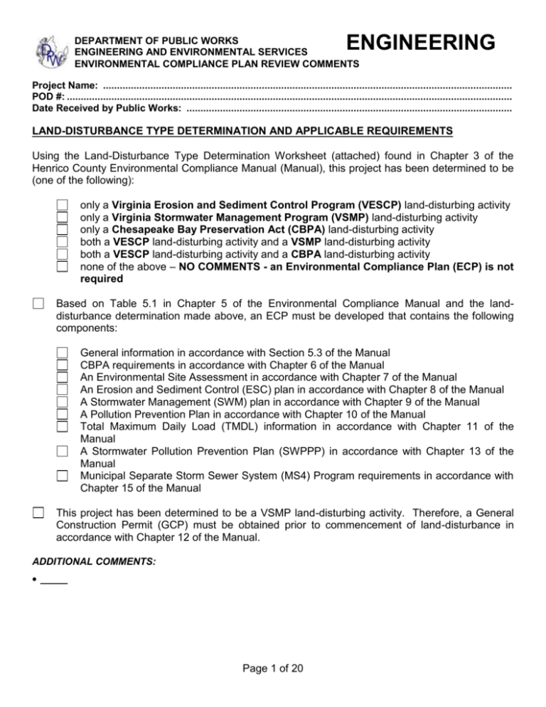
ENGINEERING DEPARTMENT OF PUBLIC WORKS ENGINEERING AND ENVIRONMENTAL SERVICES ENVIRONMENTAL COMPLIANCE PLAN REVIEW COMMENTS Project Name: ................................................................................................................................................... POD #: ................................................................................................................................................................ Date Received by Public Works: ..................................................................................................................... LAND-DISTURBANCE TYPE DETERMINATION AND APPLICABLE REQUIREMENTS Using the Land-Disturbance Type Determination Worksheet (attached) found in Chapter 3 of the Henrico County Environmental Compliance Manual (Manual), this project has been determined to be (one of the following): only a Virginia Erosion and Sediment Control Program (VESCP) land-disturbing activity only a Virginia Stormwater Management Program (VSMP) land-disturbing activity only a Chesapeake Bay Preservation Act (CBPA) land-disturbing activity both a VESCP land-disturbing activity and a VSMP land-disturbing activity both a VESCP land-disturbing activity and a CBPA land-disturbing activity none of the above – NO COMMENTS - an Environmental Compliance Plan (ECP) is not required Based on Table 5.1 in Chapter 5 of the Environmental Compliance Manual and the landdisturbance determination made above, an ECP must be developed that contains the following components: General information in accordance with Section 5.3 of the Manual CBPA requirements in accordance with Chapter 6 of the Manual An Environmental Site Assessment in accordance with Chapter 7 of the Manual An Erosion and Sediment Control (ESC) plan in accordance with Chapter 8 of the Manual A Stormwater Management (SWM) plan in accordance with Chapter 9 of the Manual A Pollution Prevention Plan in accordance with Chapter 10 of the Manual Total Maximum Daily Load (TMDL) information in accordance with Chapter 11 of the Manual A Stormwater Pollution Prevention Plan (SWPPP) in accordance with Chapter 13 of the Manual Municipal Separate Storm Sewer System (MS4) Program requirements in accordance with Chapter 15 of the Manual This project has been determined to be a VSMP land-disturbing activity. Therefore, a General Construction Permit (GCP) must be obtained prior to commencement of land-disturbance in accordance with Chapter 12 of the Manual. ADDITIONAL COMMENTS: Page 1 of 20 ENGINEERING DEPARTMENT OF PUBLIC WORKS ENGINEERING AND ENVIRONMENTAL SERVICES ENVIRONMENTAL COMPLIANCE PLAN REVIEW COMMENTS Project Name: ................................................................................................................................................... POD #: ................................................................................................................................................................ Date Received by Public Works: ..................................................................................................................... GRANDFATHERED AND PREVIOUSLY PERMITTED PROJECTS This project is neither grandfathered nor previously permitted. Application of the Technical Criteria found in Chapter 14 of the Manual (old Technical Criteria) is only allowed on grandfathered projects or projects that obtained initial GCP coverage prior to July 1, 2014 as described in Chapter 4 of the Manual. However, the Technical Criteria found in Section 9.3 of the Manual (new Technical Criteria) may be applied at the applicant’s discretion in lieu of those in Chapter 14. This project has claimed grandfathered status. Before grandfathered status can be confirmed, information verifying compliance with the following conditions must be provided: For local, state, and federal projects: There has been an obligation of funding, either in whole, or in part, prior to July 1, 2012, or a stormwater management plan for the project was approved by the Department or the Administrator prior to July 1, 2012. No General Construction Permit (GCP) was issued prior to July 1, 2014. Land-disturbance did not commence prior to July 1, 2014. For private projects: A currently valid proffered or conditional zoning plan, a preliminary or final subdivision plat, a preliminary or final site plan, zoning plan with a plan of development, a comprehensive stormwater management master plan; or any document determined to be equivalent to one of the above was approved by the Administrator by July 1, 2012. The approved document provides for a layout. The resulting activity will be compliant with the technical stormwater management requirements in Chapter 14 of the Manual. No General Construction Permit (GCP) was issued prior to July 1, 2014. Land-disturbance did not commence prior to July 1, 2014. The project has claimed initial GCP coverage was obtained prior to July 1, 2014. Provide evidence of the previously issued GCP, including project limits. This status has been confirmed based on information provided verifying compliance with the applicable conditions described in Chapter 4 of the Manual. Project status (grandfathered, previously permitted, etc.) must be identified on the cover sheet. ADDITIONAL COMMENTS: Page 2 of 20 ENGINEERING DEPARTMENT OF PUBLIC WORKS ENGINEERING AND ENVIRONMENTAL SERVICES ENVIRONMENTAL COMPLIANCE PLAN REVIEW COMMENTS Project Name: ................................................................................................................................................... POD #: ................................................................................................................................................................ Date Received by Public Works: ..................................................................................................................... ENVIRONMENTAL COMPLIANCE PLAN - GENERAL INFORMATION (Chapter 5) 1. The plan must be prepared by a professional (engineer, architect, landscape architect, or land surveyor) registered in the Commonwealth of Virginia. 2. Provide the engineer’s/surveyor’s/landscape architect’s name, address, e-mail address, telephone number, and fax number. 3. Provide the owner’s and/or developer’s name, address, e-mail address, telephone number, and fax number. 4. The plan must conform to a subdivision plat or plan of development which complies with chapters 19 or 24 of the Code. 5. A tree protection plan which complies with §24-106.2 of the Code and includes all areas designated as forest/open space on the Virginia Runoff Reduction Method (VRRM) worksheets. 6. A comprehensive drainage plan that clearly indicates items such as 1) existing and proposed drainage structures located onsite and those located offsite that will receive drainage from the project, and 3) topography and/or direction of flow. 7. Provide the GPINs of the parcels on which the regulated land-disturbing activity will occur. 8. 9. The minimum size lettering allowable on construction plans is 1/8”. Topography: (Provide on the cover sheet) Source of the topography Date of the survey Name of the Surveyor that performed or oversaw the site survey work Name of the firm that performed the site survey work 10. The latest copy of the Standard Construction Notes/Details Sheet (revised 4/14/06) must be included with the plans. 11. Provide a complete drainage area map, in acres, including all off-site drainage areas, supported by an outlined contour map. 12. A performance bond for the road and drainage improvements shown on the approved construction plans must be submitted prior to recordation of the subdivision. The bond amount for the road and drainage improvements must be determined using the bond calculation worksheet provided by the County of Henrico Department of Public Works. Submit the completed bond calculations worksheet provided by the County of Henrico Department of Public Works for the road and drainage improvements. 13. ADDITIONAL COMMENTS: STORMWATER MANAGEMENT (SWM) PLAN REQUIREMENTS (Chapter 9) 14. 15. A SWM plan in accordance with Chapter 9 of the Environmental Compliance Manual must be provided. Projects which will be submitted in phases (Section A, Section B, etc.) must address stormwater quality and quantity (where applicable) for the entire subdivision as part of the first phase submittal. BMP calculations, location(s), and design option(s) must be identified on an overall subdivision plan Page 3 of 20 ENGINEERING DEPARTMENT OF PUBLIC WORKS ENGINEERING AND ENVIRONMENTAL SERVICES ENVIRONMENTAL COMPLIANCE PLAN REVIEW COMMENTS Project Name: ................................................................................................................................................... POD #: ................................................................................................................................................................ Date Received by Public Works: ..................................................................................................................... 16. 17. 18. 19. 20. 21. 22. 23. 24. 25. 26. 27. 28. 29. 30. 31. 32. 33. and approved by the Department of Public Works prior to any phase plan approval. All pervious lands on the site must be considered to be in good hydrologic condition in accordance with the U.S. Department of Agriculture’s Natural Resources Conservation Service (NRCS) standards. Pre- and post-development site conditions and hydrology must be verified by site inspections, topographic surveys, available soil mapping or studies, and calculations consistent with good engineering practices. The Virginia Stormwater Management Handbook and the Virginia Stormwater BMP Clearinghouse provide guidance that is considered to be appropriate practices. All hydrologic analyses must be based on the ultimate development condition of the upstream drainage area (in accordance with the Planning Department’s Comprehensive Plan) and the ultimate development condition of the proposed project. Proposed residential, commercial, or industrial subdivisions shall apply these stormwater management criteria to the development as a whole. Individual lots in new subdivisions shall not be considered separate development projects, but rather the entire subdivision shall be considered a single development project. Hydrologic parameters shall reflect the ultimate development and shall be used in all engineering calculations. Provide information demonstrating that the technical criterion of this Chapter applies to the entire regulated land-disturbing activity. Provide information demonstrating that all sources of surface runoff and all sources of subsurface and groundwater flows converted to surface runoff have been considered in the development of the SWM plan. Identify the type and location of all points of discharge from the site and the type of features to which stormwater is being discharged. Show the pre-development and post-development drainage areas to each point of discharge Identify the pre-development and post-development site conditions Identify the type, location (including geographic coordinates), acres treated, and the point of discharge for each proposed stormwater management facility Provide hydrologic and hydraulic computations, including runoff characteristics Show the existing and proposed topography of the site Show the locations of existing streams, ponds, culverts, ditches, wetlands, other water bodies, and floodplains Show the location of the A, B, C, or D soil types, forest cover, and other vegetated areas used in the Virginia Runoff Reduction Method worksheets must be clearly shown on the plans. Identify the locations of existing and proposed structures, roads, utilities and easements Show the limits of the regulated land-disturbing activity Provide tabulations of the areas devoted to impervious, forest/open and other vegetative cover based on both the existing and proposed site conditions Identify and delineate all 6th order Hydrologic Unit Codes (HUCs). ADDITIONAL COMMENTS: Page 4 of 20 ENGINEERING DEPARTMENT OF PUBLIC WORKS ENGINEERING AND ENVIRONMENTAL SERVICES ENVIRONMENTAL COMPLIANCE PLAN REVIEW COMMENTS Project Name: ................................................................................................................................................... POD #: ................................................................................................................................................................ Date Received by Public Works: ..................................................................................................................... STORMWATER QUALITY INFORMATION (Section 9.3.2-3) This project is considered: New Development – The complete Virginia Runoff Reduction Method (VRRM) New Development Worksheet must be submitted for review. Development on Prior-Developed Lands – The Virginia Runoff Reduction Method ReDevelopment Worksheet must be submitted for review. Provide the VRRM summary sheet on the plans. 34. Areas designated as forest/open space in the VRRM worksheets must be shown as tree-protection areas. 35. The following information contained in the VRRM worksheets is incorrect and must be revised: 36. 37. 38. 39. 40. Compliance with the pollutant removal requirements is achieved by: Proposed on-site SWM facilities Existing on-site SWM facilities Proposed off-site SWM facilities Existing off-site SWM facilities Nutrient offsets Off-site options that are not being constructed as part of this plan must be existing or under construction prior to plan approval. Nutrient offsets are not allowed unless one of the following conditions are met: 1. The project results in less than five acres of land disturbance. 2. The post-construction phosphorus nutrient reduction requirement is less than 10 pounds per year 3. At least 75% of the required phosphorus nutrient reduction requirement is achieved onsite, OR: a. Alternative site designs have been considered that may accommodate on-site best management practices, b. On-site best management practices have been considered in alternative site designs to the maximum extent practicable, c. Appropriate on-site best management practices will be implemented, AND d. Full compliance with post-development non-point nutrient runoff compliance requirements cannot be practicably met on-site. A separate SWM facility review checklist is provided for comments regarding each proposed permanent SWM facility. The following information must be provided for each existing permanent SWM facility that is used to demonstrate compliance: Information to show that the SWM facility was designed in accordance with the existing Part IIC technical criteria The land-use conditions for the proposed project upon which the SWM facility was designed The proposed land-use conditions for the project area that the SWM facility serves Page 5 of 20 ENGINEERING DEPARTMENT OF PUBLIC WORKS ENGINEERING AND ENVIRONMENTAL SERVICES ENVIRONMENTAL COMPLIANCE PLAN REVIEW COMMENTS Project Name: ................................................................................................................................................... POD #: ................................................................................................................................................................ Date Received by Public Works: ..................................................................................................................... 41. 42. Because the land-use conditions have changed since the original SWM facility design, the existing SWM facility must be modified to comply with the new Part IIB technical criteria A letter of availability from the off-site provider must be included in the plans for each offsite compliance measure (SWM facility or nutrient offset) used to demonstrate compliance: The following information must be included on the plans if nutrient offsets are being used to demonstrate compliance: Letter of final authorization (a letter from the permit issuing authority to the buyer outlining conditions pursuant to the use of an offset) Notarized affidavit of offset sale Proof of perpetuity of the offset (a copy of the recorded covenants, restrictions, easement, or other appropriate instrument verifying the stormwater nutrient offsets that have been acquired to meet the construction activity’s required nutrient reductions will be protected in perpetuity) ADDITIONAL COMMENTS: CHANNEL PROTECTION (Section 9.3.4) 43. Complete the Channel Protection Compliance Summary table on the Erosion and Sediment Control – Standard Details/Calcs. sheet for each discharge point. 44. Provide supporting information for all values included in the Channel Protection Compliance Summary table. 45. There is a manmade stormwater conveyance system below discharge point(s) Channel Protection Compliance Summary table accordingly. . Revise the 46. There is a restored stormwater conveyance system below discharge point(s) Channel Protection Compliance Summary table accordingly. . Revise the 47. There is a natural stormwater conveyance system below discharge point(s) . Revise the Channel Protection Compliance Summary table to demonstrate compliance with the Energy Balance requirement. ADDITIONAL COMMENTS: FLOOD PROTECTION (Section 9.3.5) 48. All locations where concentrated stormwater flows that (i) contain runoff from the land-disturbing activity, (ii) are created as a result of the land-disturbing activity, or (iii) are increased as a result of the land-disturbing activity (discharge points) must be released into a stormwater conveyance system must be clearly identified on the plans 49. Each stormwater conveyance system receiving concentrated stormwater flow must be analyzed from the discharge point to a point where either: a. The site’s contributing drainage area is less than or equal to 1.0% of the total watershed area; OR Page 6 of 20 ENGINEERING DEPARTMENT OF PUBLIC WORKS ENGINEERING AND ENVIRONMENTAL SERVICES ENVIRONMENTAL COMPLIANCE PLAN REVIEW COMMENTS Project Name: ................................................................................................................................................... POD #: ................................................................................................................................................................ Date Received by Public Works: ..................................................................................................................... b. The site’s peak flow rate from the one-year 24-hour storm is less than or equal to 1.0% of the existing peak flow rate from the one-year 24-hour storm prior to the implementation of any stormwater quantity control measures. 50. 51. The limits of analysis for each discharge point must be clearly shown on the plans. Provide supporting information to indicate how the limits of analysis were determined. 52. Complete the Flood Protection Compliance Summary table on the Erosion and Sediment Control – Standard Details/Calcs. sheet for each discharge point. 53. Provide supporting information for all values included in the Flood Protection Compliance Summary table. 54. There is evidence of localized flooding below discharge point(s) Compliance Summary table accordingly. . Revise the Flood Protection ADDITIONAL COMMENTS: 50/10 DETENTION (Section 9.3.6) 55. This project falls within the limits of a 50/10 detention area. Provide supporting calculations to show that the post-developed peak flow from the site for a 50-year-24hr storm event does not exceed the pre-developed peak flow rate for a 10-year-24hr storm event. 56. 57. Complete the 50/10 detention requirements summary table on the ESC/ESA sheet. This project may opt out of the 50/10 detention requirements if information is provided showing that there are no existing homes located within the 50-year floodplain downstream of the proposed development. ADDITIONAL COMMENTS: INCREASED VOLUMES OF SHEET FLOW (Section 9.3.7) 58. Increased sheet flow volumes resulting from the land-disturbing activity must be identified and evaluated for potential impacts to downstream properties or resources. 59. Increased sheet flow volumes that will cause or contribute to erosion, sedimentation, and/or flooding of downstream properties or resources must be diverted to a SWM facility or stormwater conveyance system that conveys the runoff without causing erosion, sedimentation, or flooding. ADDITIONAL COMMENTS: DESIGN STORMS AND HYDROLOGIC METHODS (Section 9.3.8) 60. The prescribed design storms are the 1-year, 2-year, and 10-year 24-hour storms using the site specific rainfall precipitation frequency data recommended by the U.S. National Oceanic and Page 7 of 20 ENGINEERING DEPARTMENT OF PUBLIC WORKS ENGINEERING AND ENVIRONMENTAL SERVICES ENVIRONMENTAL COMPLIANCE PLAN REVIEW COMMENTS Project Name: ................................................................................................................................................... POD #: ................................................................................................................................................................ Date Received by Public Works: ..................................................................................................................... Atmospheric Administration (NOAA) Atlas 14. precipitation data. Partial duration time series shall be used for the 61. The U.S. Department of Agriculture’s Natural Resources Conservation Service (NRCS) synthetic 24hour rainfall distribution and models must be used to conduct the hydrologic analyses. These include, but are not limited to TR-55 and TR-20, hydrologic and hydraulic methods developed by the U.S. Army Corps of Engineers, or other standard hydrologic and hydraulic methods. 62. The Rational Method may only be used to evaluate peak discharges for drainage areas of 200 acres or less. The Modified Rational Method may only be used for evaluating volumetric flows to stormwater conveyances for drainage areas of 200 acres or less. 63. ADDITIONAL COMMENTS: SWM FACILITY MAINTENANCE (Section 9.5) 64. 65. Individual maintenance agreements are required for each SWM facility type prior to plan approval. See individual SWM facility comment sheets for further information. A maintenance fund payment of $100.00 per lot per SWM facility must be paid prior to subdivision recordation. ADDITIONAL COMMENTS: GENERAL CONSTRUCTION PERMIT (GCP) (Chapter 12) 66. A General Construction Permit (GCP) is required for the proposed land-disturbing activity. 67. A draft Registration Statement must be submitted for all proposed VSMP land-disturbing activities as part of the plan submittal and review process. 68. Submit a final copy of the Registration Statement with the required signatures to the Review Engineer. 69. The Registration Statement indicates an estimated land disturbance amount of acres. Based on this amount, a GCP Issuance Fee of $ must be submitted to the Department of Public Works prior to plan approval. This fee includes the State of Virginia’s portion of the Permit Issuance Fee. ADDITIONAL COMMENTS: STORMWATER POLLUTION PREVENTION PLAN (SWPPP) (Chapter 13) 70. A Stormwater Pollution Prevention Plan (SWPPP) is required for all proposed VSMP land-disturbing activities. Page 8 of 20 ENGINEERING DEPARTMENT OF PUBLIC WORKS ENGINEERING AND ENVIRONMENTAL SERVICES ENVIRONMENTAL COMPLIANCE PLAN REVIEW COMMENTS Project Name: ................................................................................................................................................... POD #: ................................................................................................................................................................ Date Received by Public Works: ..................................................................................................................... 71. The following information must be provided so that it can be included in the SWPPP binder that will be distributed at the pre-construction meeting: Tab 1 - SWPPP title sheet Tab 3 - Required SWPPP Components table Tab 4 - SWPPP narrative Tab 7 – ECP and Other Incorporated Plans Tab 8 - Pollution Prevention Plan Information Tab 9 - TMDL table 9.1 SWM facility information sheets ADDITIONAL COMMENTS: TECHNICAL CRITERIA FOR GRANDFATHERED & PREVIOUSLY PERMITTED PROJECTS (Chapter 14) 72. The following worksheets (if checked) must be corrected/completed and submitted to the Department of Public Works and also included in the plans. Worksheet 14.09 – Program Implementation Worksheet 14.06 – Urban Management Area Opt In Worksheet 14.08 – Environmental Fund Contribution Worksheet 14.07 – Compliance Worksheet 14.01 – Situation One, Worksheet 14.02 – Situation Two, Worksheet 14.03 – Situation Three, Worksheet 14.04 – Situation Four, or Worksheet 14.05 – Situation Five BMP design worksheet 73. 74. Provide an overall/master plan showing the phasing of sections and proposed BMP locations with supporting calculations. The appropriate Stormwater Pollutant Removal worksheet is needed to determine whether the calculated pollutant removal requirement must be achieved through 1) a contribution to the Environmental Fund or participation in a regional BMP or 2) must be achieved in an on-site BMP or a regional BMP. 75. The plan must demonstrate that the calculated pollutant removal requirement is achieved in an onsite BMP or a regional BMP. 76. The calculated pollutant removal requirement must be achieved through a contribution to the Environmental Fund or participation in a regional BMP. 77. Contributions to the Environmental Fund must be made prior to plan approval. 78. Contributions to the Environmental Fund must be made prior to recordation of the subdivision. 79. This project falls within the limits of a 50/10 detention area. Provide supporting calculations to show that the post-developed peak flow from the site for a 50-year storm event does not exceed the predeveloped peak flow rate for a 10-year storm event. 80. 81. Complete the 50/10 detention requirements summary table on the ESC/ESA sheet. Provide the following information for all 50/10 detention basins: Construction details for the basin, embankment, and outlet devices Storm routings for the 10-, 50-, and 100-year storm Page 9 of 20 ENGINEERING DEPARTMENT OF PUBLIC WORKS ENGINEERING AND ENVIRONMENTAL SERVICES ENVIRONMENTAL COMPLIANCE PLAN REVIEW COMMENTS Project Name: ................................................................................................................................................... POD #: ................................................................................................................................................................ Date Received by Public Works: ..................................................................................................................... Delineate the normal pool and 100-year storm elevations Delineate the 50-year storm elevation for all 50/10 detention basins Contributing drainage areas Calculations for time of concentration, curve number, and/or runoff coefficients Complete input for hydrograph generation Stage/storage table Stage/discharge for each component of the outlet structure Composite stage/discharge table Outlet control analysis Provide evidence that the 50-year storm will remain on the site until it reaches the basin Side slopes must be clearly labeled on the plans. 82. Provide the following information for all BMP basins: Construction details for the basin, embankment, and outlet devices Delineate the normal pool and 100-year storm elevations Contributing drainage areas Stage/storage table Side slopes must be clearly labeled on the plans. 83. Existing wet ponds in single-family residential subdivisions are permitted to remain, however, the subdivision must be designed in such a manner that the existing pond(s) meet each of the following criteria (checked items must be addressed): The pond(s) must be located in common area. There must be at least 50 feet between the normal pool elevation of the pond(s) and any buildable area. A 20’ wide access easement must be provided to the pond(s). The easement must be completely on one property (it can not straddle a property line). The access easement must provide access to all inlet and outlet structures in the pond(s). Show the normal pool elevation in the pond(s). A 16’ wide drainage easement is required from all inlets to the outlet(s) if the pond contains public water. Provide the 10-year, and 100-year elevations in the pond(s). Show that the pond has an adequate outfall in accordance with MS-19. Provide a dam break analysis if the dam is constructed of fill. 84. All BMPs must be designed in accordance with the minimum standards set forth in the Henrico County Environmental Program Manual. 85. The BMP/SWM facility must be located as follows: The highest continuous contour on the inside of the basin must be located at least 25’ from the right-of-way limits for commercial projects. The highest continuous contour on the inside of the basin must be located outside of the front yard setback for subdivisions and must be at least 25’ from the right-of-way in the side yard. Structural BMPs that are visible from the right-of-way must be located at least 25’ from the right-of-way limits. 86. Provide a maintenance schedule for all manufactured BMP structures on the plans. 87. Clearly label the dimensions of all BMPs on the plans. Page 10 of 20 ENGINEERING DEPARTMENT OF PUBLIC WORKS ENGINEERING AND ENVIRONMENTAL SERVICES ENVIRONMENTAL COMPLIANCE PLAN REVIEW COMMENTS Project Name: ................................................................................................................................................... POD #: ................................................................................................................................................................ Date Received by Public Works: ..................................................................................................................... 88. A BMP maintenance fee of $100.00 per lot is required prior to recordation for subdivisions that drain to a BMP that will be maintained by a Homeowners Association. This does not apply to wet ponds since the County assumes no maintenance responsibility for wet ponds. 89. To evaluate whether or not dams/impoundments are subject to the Virginia Dam Safety Act, Article 2, Chapter 6, Title 10.1 of the Code of Virginia and Dam Safety Regulations, the following information must be provided: dam height (vertical distance from the streambed at the downstream toe to the top of dam) the impoundment capacity (the volume capable of being impounded at the top of the dam) 90. The dam/impoundment appears to be exempt from the Virginia Dam Safety Act, Article 2, Chapter 6, Title 10.1 of the Code of Virginia and Dam Safety Regulations because: the dam height is less than 6 feet, or the capacity is less than 50 acre-feet and the dam height is less than 25 feet, or the capacity is less than 15 acre-feet and the dam height is more than 25 feet 91. The dam/impoundment appears to be subject to the Virginia Dam Safety Act, Article 2, Chapter 6, Title 10.1 of the Code of Virginia and Dam Safety Regulations. Regulated dams/impounding structures cannot be constructed or altered prior to issuance of a Virginia Soil and Water Conservation Board construction permit. Contact the Virginia Department of Conservation and Recreation at (804) 371-6095. 92. If the dam height is greater than three (3), a geotechnical certification must be submitted in accordance with Section 3-14 of the Henrico County Design Manual stating that construction compaction requirements have been achieved. This must be submitted as part of the BMP as-built certification prior to ESC bond release. Complete the “Outfall Adequacy” table on the ESC/ESA sheet. All sediment basins/traps must drain to an adequate outfall in accordance with MS-19. Provide supporting information on the plans to show that this requirement is being met. 93. 94. 95. 96. For all existing channels, wetland systems, and/or culverts used as an outfall, provide the following information: A profile based on field-run elevations beginning at the project’s discharge location and extending no less than 150 feet in length downstream of the property boundary. The profile may need to be extended to include all identified channel/wetland/culvert constrictions beyond 150 feet. Cross-sections every 50 feet along the required length of the profile at the most constricted locations. Identification of the size, material and type of all structures along the profile Scale must be 1”:1’ Vertical, 1”:5’ Horizontal For all existing storm sewer systems used as an outfall, provide the following information: A profile based on field-run elevations beginning at the project’s discharge location and including the existing pipe to the first structure (inlet, manhole, etc.) downstream of the project boundary. Identification of the size, material and type of all structures along the profile 97. To verify the adequacy of a channel used as an outfall, the following information must be provided: Page 11 of 20 ENGINEERING DEPARTMENT OF PUBLIC WORKS ENGINEERING AND ENVIRONMENTAL SERVICES ENVIRONMENTAL COMPLIANCE PLAN REVIEW COMMENTS Project Name: ................................................................................................................................................... POD #: ................................................................................................................................................................ Date Received by Public Works: ..................................................................................................................... Q2 Q10 Qcapacity V2 Vallowable The 10-year storm flow is not contained within the channel. Therefore, the channel is not adequate. The velocity associated with the 2-year storm flow exceeds the allowable velocity. Therefore, the channel is not adequate. 98. To verify adequacy of a wetland system used as an outfall, the following information must be provided: Q10 99. Qcapacity (within the limits of the wetlands) V2 Vallowable The 10-year storm flow is not contained within the limits of the wetland system. Therefore, the wetland system is not adequate. The velocity associated with the 2-year storm flow exceeds the allowable velocity. Therefore, the wetland system is not adequate. The wetland system does not appear to have an outlet and will act as an impoundment. Therefore, the wetland system is not adequate. To verify adequacy of a storm sewer system or culvert used as an outfall, the following information and supporting calculations must be provided: Q10 Qcapacity Submit the storm sewer design spreadsheets Hydraulic gradeline calculations for the 10-year storm Culvert analysis for the 10-year storm using standard VDOT form The existing storm sewer or culvert does not have adequate capacity for the 10-year storm flow. Therefore, the existing storm sewer or culvert is not adequate. 100. In order to use the floodplain as an outfall, the following information must be provided: Stormwater must be discharged at the limits of the floodplain using an energy dissipator in accordance with Minimum Standard 9.01 of the Henrico County Environmental Program Manual, OR an adequate channel must be provided from the project’s discharge location to the existing channel in the floodplain. The following information must be provided: Q10 Qcapacity V2 Vallowable The 10-year storm flow is not contained within the channel. Therefore, the outfall is not adequate. The velocity associated with the 2-year storm flow exceeds the allowable velocity. Therefore, the channel is not adequate. The stormwater does not enter the floodplain in a sheet flow manner. Therefore, the outfall is not adequate. ADDITIONAL COMMENTS: ROAD DESIGN: 101. Provide classifications for all roads. Include the projected vehicles per day (VPD) for all roads. Page 12 of 20 ENGINEERING DEPARTMENT OF PUBLIC WORKS ENGINEERING AND ENVIRONMENTAL SERVICES ENVIRONMENTAL COMPLIANCE PLAN REVIEW COMMENTS Project Name: ................................................................................................................................................... POD #: ................................................................................................................................................................ Date Received by Public Works: ..................................................................................................................... Provide the typical section for all roads as provide in the Design Manual Provide pavement sections for all roads that match the road classification. 102. 103. 104. Provide a minimum 50’ vertical curve to tie the proposed road grade into the existing edge of pavement at intersections. Provide K-values for all vertical curves in accordance with the Design Manual. Also, show the design speed for all roadways. A six (6) feet wide pedestrian shelf is required behind all curb and gutter in the County right-of-way. 105. Curb and gutter, pavement widening, and related drainage items are required along all frontage on public rights-of-way. 106. Show the full typical section for pavement widening on the plans, showing the centerline of pavement, right-of-way limits, proposed pavement width, elevations, grade percentage, and underdrains. Provide cross-sections, at a minimum of 25 feet intervals, showing the existing and proposed pavement elevations throughout the limits of all pavement widening. All existing and proposed crossslopes must be provided, as well as pavement overlays and milling. (All cross-sections must be shown at a scale of 1”:1’ vertical and 1”:25’ horizontal.) Pavement cross-sections for road widening must meet the following criteria: 107. 108. Minimum proposed cross slope is 1.5% Maximum proposed cross slope is 3.0% There can be no more 1.0% difference between the existing and proposed pavement cross slopes 109. Pavement overlays, pavement buildup, and/or milling, must be clearly shown on the plans. When overlays are required in curb and gutter sections, the curb lanes must be edge milled prior to the overlay to eliminate pavement build-up at the edge of pavement and to provide a smooth tie-in to the edge of gutter. In ditch sections, shoulders and driveways must be tied into the finished elevation of the pavement overlay. 110. Provide profiles along the full length of widening showing the road centerline, existing edge of pavement, and proposed top of curb. The profile must include all drainage structures within the rightof-way. (All profiles must be shown at a scale of 1”:1’ vertical and 1”:50’ horizontal.) 111. All proposed curb and gutter must have a minimum 0.3% longitudinal slope. 112. Provide cross-sections of the roadway showing the limits of pavement, curb and gutter, guard rail, end treatments, fill slopes, easement limits, and any drainage structures at all locations where Traffic Engineering is requiring guard rail. UD-4 underdrains are required along the entire length of all proposed roads and/or road widening within the public right-of-way unless waived by the Director of Public Works. 113. 114. UD-2 underdrains are required in all raised grass medians and islands located in the public right-ofway. 115. 116. CD-1 underdrains are required for all vertical sags located within the public right-of-way. Show the location of all underdrains on the plans. 117. Private roads and driveways within multi-family developments should be constructed in accordance with County roadway pavement standards. Provide projected vehicles per day and pavement sections for all private roads and driveways. Page 13 of 20 ENGINEERING DEPARTMENT OF PUBLIC WORKS ENGINEERING AND ENVIRONMENTAL SERVICES ENVIRONMENTAL COMPLIANCE PLAN REVIEW COMMENTS Project Name: ................................................................................................................................................... POD #: ................................................................................................................................................................ Date Received by Public Works: ..................................................................................................................... ADDITIONAL COMMENTS: GRADING: 118. The following issues must be addressed regarding lot grading: An overall (one page) lot drainage map must be included in all subdivision plans at a minimum scale of 1”=200’, and must include the following: Flow direction arrows for each lot Show the minimum finished floor elevation (MFF) for each lot based on the required grading to ensure proper drainage. House locations must be shown for all lots with grading plans. The MFF must be at least 3.0 feet above finished grade. Lots which have special building permits requirements must be identified on the construction plans as follows: NBP1, NBP2, NBP3. NBP1 – All areas of required grading (including low-lying areas and wetlands to be impacted) and drainage swales, as indicated on the plans, shall be constructed concurrently with the road construction. Certification of the construction by the engineer of record is required prior to issuance of Building Permits for lots identified as NBP1. The required certification must be attached to the Building Permits for these lots. This applies to lots . NBP2 – All lots that include storm sewer. A certified plat identifying the storm sewer easement and the location of the installed drainage improvements must be submitted by the engineer of record prior to the issuance of a Building Permit for those lots identified as NBP2. (NOTE: Lots not built on by the time of road acceptance must have the easements staked and flagged for review prior to road acceptance). The required certification must be attached to the Building Permits for these lots. This applies to lots . NBP3 – All lots that contain or are adjacent to lots that contain sediment basins/traps. Building permits will be delayed until the sediment basins/traps are removed. Add a note to the plans stating that all lots are to be graded at the time of road construction. Provide the Building Permit Special Requirements table (a summary of the above information) on the cover sheet. 119. Show all existing and proposed contours at a maximum interval of two feet (i.e.: road fill/cut, lot grading, wetland/WOUS grading, etc.). ADDITIONAL COMMENTS: CURB AND GUTTER / STORM SEWER: 120. Curb and gutter is required on both sides of each road in the subdivision if any of the following apply: There is less than 0.5% grade within any block of any road in the subdivision. 25% of the roads within a subdivision have 1.0% or flatter grade. 25% of the lots within a subdivision have less than 80 feet of road frontage. Page 14 of 20 ENGINEERING DEPARTMENT OF PUBLIC WORKS ENGINEERING AND ENVIRONMENTAL SERVICES ENVIRONMENTAL COMPLIANCE PLAN REVIEW COMMENTS Project Name: ................................................................................................................................................... POD #: ................................................................................................................................................................ Date Received by Public Works: ..................................................................................................................... 121. Henrico County Curb and Gutter is required around all temporary cul-de-sacs. 122. Roll-faced curb is only allowed on roadways that are Class I-IV (0-1000 VPD). The pavement width must be at least 32’ (36’ f/c-f/c). 123. If roll-faced curb is used, two (2) inlets with 100% collection efficiency must be provided on both sides of the road on descending grades before all cul-de-sacs with descending grades. 124. Provide CG-12 curb ramps at all intersections where there is existing or proposed sidewalk. Provide depressed curb at intersections if no sidewalk is proposed. 125. Provide top of curb elevations around: 126. All entrances must be CG-9D and labeled as such on the plans. 127. 128. Roll-faced curb is not allowed for parking areas. The maximum depth of flow along roll-faced curb is four inches. 129. Curb cuts are not permitted along drive aisles. 130. All medians less than six feet wide must be VDOT Std. MS-1. For turn lanes being constructed on existing roads, the old median must be removed entirely and the solid raised median poured on the asphalt base course in accordance with the standards for MS-1 Median. Standard MS-1A or variations of the same are not be permitted. 131. Valley gutters are not allowed in the public right-of-way. 132. Provide profiles based on field-run elevations for all storm sewers located outside of the right-of-way limits. 133. 134. Provide an itemized list (including descriptions) of all drainage structures on the plan. Stormwater must be collected on-site in curb drop inlets. 135. Provide the following information for all curb and gutter/storm sewer systems: all cul-de-sacs all curb returns Depth and spread in all gutters based on a two-year storm. Length of inlet throats (sized for 10-year storm) Inlet placement based on the maximum allowable spread during a 2-year storm Type of material (RCP Class III or better in County easements or right-of-way) Diameter (minimum 15 inches) Velocity (minimum allowable of 2 fps for 2-year storm) (maximum of 15 fps for 10-year storm) Capacity (based on 10-year storm event) Hydraulic grade line computations noting elevations at key points (drop inlets, manholes, etc.)(indicate where inlet shaping is to take place) including details showing how the starting water surface elevation was obtained Concrete flume transition details from curb to ditch Details of non-standard structures Longitudinal slope (minimum allowable is 0.3%) Maximum length between structures is 300 feet for pipes less than 48” diameter Indicate whether inlet shaping, steps, and/or O-ring pipe are proposed Provide storm sewer information/calculations in tabular format on the plans. 136. Provide adequate cover for all storm sewers. The minimum allowable cover is: Nine (9) inches for storm sewer in the right-of-way Six (6) inches for storm sewer in easements Page 15 of 20 ENGINEERING DEPARTMENT OF PUBLIC WORKS ENGINEERING AND ENVIRONMENTAL SERVICES ENVIRONMENTAL COMPLIANCE PLAN REVIEW COMMENTS Project Name: ................................................................................................................................................... POD #: ................................................................................................................................................................ Date Received by Public Works: ..................................................................................................................... 137. Provide the following information for all culverts: Inverts based on field-run elevations Lengths Type (RCP Class III or better in County easements or right-of-way) Headwater calculations Inlet and outlet protection Outlet velocity (10-year storm) Diameter Design cover Provide the completed VDOT standard culvert form 138. DI-3 series inlets must be designed so that the minimum depth of the inlets is equal to or greater than the diameter of the pipe plus 2.67’ (32”). 139. DI-4 series inlets are required for all storm sewers greater than 30” diameter. 140. 141. The maximum throat length for curb drop inlets in cul-de-sacs is six feet. Drop inlets are not allowed in the radius of intersections. 142. No more than 0.5 cfs may be directed onto a public right-of-way during a 10-year storm. 143. Provide details for JB-1 and any non-standard VDOT inlets. 144. All outlet protection must be designed in accordance with Std. & Spec. 3.18 of the Virginia Erosion and Sediment Control Handbook, Third Edition, 1992. 145. Show the dimensions for all outlet protection (length, width, and depth, including filter fabric lining). ADDITIONAL COMMENTS: ON-SITE CHANNELS / WETLANDS: 146. All channels with less than 100 acres of contributing drainage area must be piped or otherwise eliminated. If the environmental regulatory agencies will not issue a permit to impact jurisdictional channels that fall under this policy, the standard form letter attached to the September 12, 2005 policy letter must be completed and submitted and copies sent to the appropriate environmental regulatory agency. 147. Open channels, except for roadside ditches, are not permitted unless specifically mandated by local, state and/or federal requirements. 148. Provide a typical yard swale detail. All yard swales must meet the following criteria: Longitudinal slope must be at least 1% Minimum side slope ratio is 3:1 Maximum depth is 18 inches No longer than 150 feet without a drop inlet 149. Provide a cross-section for all channels (existing and proposed, natural and man-made) used for stormwater conveyance. Additional cross-sections will be required where channel characteristics change. The following information must accompany each cross-section: Depth Side slopes (no steeper than 3:1 for proposed channels) Page 16 of 20 ENGINEERING DEPARTMENT OF PUBLIC WORKS ENGINEERING AND ENVIRONMENTAL SERVICES ENVIRONMENTAL COMPLIANCE PLAN REVIEW COMMENTS Project Name: ................................................................................................................................................... POD #: ................................................................................................................................................................ Date Received by Public Works: ..................................................................................................................... Channel Lining (with Manning’s “n” value) Flow elevations for the 2-year, 10-year and 100-year (if applicable) storm events The limits of wetlands on both sides of the channel Longitudinal slope (minimum 1.0% for proposed non-paved channels, minimum 0.3% for proposed paved channels) Scale must be 1”:1’ Vertical, 1”:5’ Horizontal 150. The following information and supporting calculations must be provided for each cross-section provided for all channels (existing and proposed, natural and man-made) used for stormwater conveyance: Q2 Q10 V2 d10 Q100 Qcapacity 151. The minimum allowable V2 for paved channels is 2 fps. 152. 153. Provide a profile based on field-run elevations for all channels used for stormwater conveyance. The following information and supporting calculations must be provided for all wetland systems: Q10 Qcapacity (within the limits of the wetlands) V2 Vallowable The limits of the 10-year storm must be delineated on the plan view in relation of the limits of the wetlands. Demonstrate that the wetland system has an outlet and will not act as an impoundment. Provide a profile based on field-run elevations for all wetland systems used for stormwater conveyance. 154. Provide a profile of the roadside ditches on the Road Profile Sheet. ADDITIONAL COMMENTS: FLOODPLAIN: 155. This site contains a 100-year floodplain designated as: FEMA Zone AE FEMA Zone A (not detailed) FEMA floodway County floodplain Zone AE County floodplain Zone A (not detailed) 100 acre drainage area without identified floodplain The floodplain boundary must appear on the plans. 156. This site contains a 100-year floodplain associated with a stream that has at least 100 acres of drainage area. The presence of this stream indicates a portion of this site is subject to flooding during a 100-year storm event. The associated floodplain and flood elevation must be reflected in the design of this development. 157. The elevation for the floodplain has not been established for the proposed project area. A floodplain study must be submitted and approved to establish the 100-year floodplain elevation. Studies for the FEMA floodplain must be approved by FEMA and appropriate documentation must be submitted to the County. Page 17 of 20 ENGINEERING DEPARTMENT OF PUBLIC WORKS ENGINEERING AND ENVIRONMENTAL SERVICES ENVIRONMENTAL COMPLIANCE PLAN REVIEW COMMENTS Project Name: ................................................................................................................................................... POD #: ................................................................................................................................................................ Date Received by Public Works: ..................................................................................................................... 158. The project site contains or is adjacent to a 100-year floodplain. This delineation must be honored in the design and layout of this project. Specifically, proposed lots must contain adequate buildable area outside the floodplain, proposed residential structures must be outside the floodplain, and finished floor elevations must be at least one foot higher than the adjacent floodplain elevation. 159. All applicable floodplain designations must be shown on the plans. limitations/elevations will govern. 160. Provide the elevations of all applicable 100-year floodplains within the project limits. 161. Delineate and provide the 100-year backwater elevation at all roadway/culvert crossings on the plans. 162. The 100-year storm may not overtop the centerline of the road by more than six inches. 163. All revisions to the FEMA floodplain must be submitted to the Federal Emergency Management Agency. Confirmation of FEMA approval must be submitted to the Department of Public Works prior to plan approval. 164. Provide the following for all proposed fill to be placed within the 100-year floodplain: The most restrictive Adequate compensating cut Cross-sections every 25 feet throughout the limits of cut and fill Cut and fill volumes Limits of cut and fill Evidence that FEMA has approved or conditionally approved any placement of fill within the FEMA floodplain limits Evidence that the proposed fill will not cause the 100-year floodplain elevation to increase 165. Label the limits of the 100-year floodplain as “variable width drainage and utility easement” and “Special Flood Hazard Area”. ADDITIONAL COMMENTS: SURVEY: 166. Provide four (4) reference coordinate points tied to the Geodetic Control Network (GCN) with coordinates in the Virginia State Plane Coordinate System (distributed near the corners of the site). All features must be tied to the four reference points (if floating on the site, they must be tied to a property corner or property line in two different locations). All County GIS monuments within the site must be identified on the plans. 167. A minimum of two benchmarks must be established and shown on the construction plans in areas that will not be disturbed during construction. For linear projects such as road widening, benchmarks must be placed no farther apart than 500 feet and tied into the survey base line. 168. Right-of-way and baseline must be established in the field by the consultant and clearly shown on the plans. They must be clearly tied to monuments/benchmarks. 169. 170. Provide stations at the centerline of all drainage structures located within the right-of-way limits. All utility poles, fire hydrants, and other above ground obstacles located within the public right-of-way and in conflict with the proposed sidewalk shelf, curb and gutter and/or the pavement widening shall be relocated at the developer’s expense prior to Henrico County staking the curb and gutter. Page 18 of 20 ENGINEERING DEPARTMENT OF PUBLIC WORKS ENGINEERING AND ENVIRONMENTAL SERVICES ENVIRONMENTAL COMPLIANCE PLAN REVIEW COMMENTS Project Name: ................................................................................................................................................... POD #: ................................................................................................................................................................ Date Received by Public Works: ..................................................................................................................... ADDITIONAL COMMENTS: EASEMENTS / AGREEMENTS: 171. Show the location, width, and recordation information for all existing drainage easements. 172. All proposed drainage easements must be a minimum of 16 feet wide. 173. The Deed Book and Page Number must be provided for all proposed off-site drainage easements prior to plan approval. 174. For commercial/multi-family projects, only runoff that is considered “public” can be contained in a County maintained drainage easement. Stormwater from off-site drainage areas that do not contain “public” water must be contained in private drainage easements. 175. Provide a drainage easement through all lakes, ponds, and/or BMP basins that will contain public water. The easement must be at least 16 feet wide and must take the most direct route from the inlet(s) to the outlet(s). Provide a BMP/SWM Maintenance Agreement. This agreement can be found on the Department of Public Works web page at: http://www.co.henrico.va.us/works/newdpwweb/Forms2/AdobeForms/BMP-SWM-form.pdf. 176. 177. A maintenance agreement must be provided between the developer and the County of Henrico prior to plan approval for irrigation, landscaping, lighting, stamped pavers, etc. within the County right-ofway. This agreement can be found on the Department of Public Works web page at: http://www.co.henrico.va.us/works/newdpwweb/RWMaintenanceAgreement.pdf. 178. Provide documentation from all private utility companies (power, gas, etc.) that authorizes land disturbance within their easements. 179. Provide evidence (copies of certified letters) that property owners have been notified that work is/will be conducted in the off-site drainage easement located on their property. ADDITIONAL COMMENTS: MISCELLANEOUS: 180. 181. Show the size and location of all existing drainage structures, pipes, roof drains, swales, ditches, curbs, and channels and the direction of flow in each. Show the location of all roof drains and pipes conveying runoff from roof areas and landscape areas. 182. The drainage system conveying runoff from roof areas and landscape areas in the vicinity of the building must be designed in accordance with the current edition of the International Plumbing Code. The following statement must be added to the plans: The roof / landscape drainage system has been designed in accordance with the current edition of the International Plumbing Code. 183. Provide material type, size and elevations for all pipes and structures in the roof / landscape drainage system. Page 19 of 20 ENGINEERING DEPARTMENT OF PUBLIC WORKS ENGINEERING AND ENVIRONMENTAL SERVICES ENVIRONMENTAL COMPLIANCE PLAN REVIEW COMMENTS Project Name: ................................................................................................................................................... POD #: ................................................................................................................................................................ Date Received by Public Works: ..................................................................................................................... 184. The drainage system conveying runoff from roof areas and landscape areas in the vicinity of the building must tie into the storm sewer system at a structure (inlet, manhole, junction box, etc.). 185. Provide details for all retaining walls. Add the following note to the plans: “Plan approval does not include approval of the retaining wall design. Contact the Department of Building Inspections for approval requirements of the retaining wall. Building Inspections will determine the retaining wall design approval”. A professional seal is required if the retaining wall is in the right-of-way. 186. Provide evidence that VDOT has reviewed the current scope of work shown on the plan and has no comments regarding the proposed work. 187. Additional comments may follow upon review of a subsequent submittal. ADDITIONAL COMMENTS: The Engineering Section has completed its review and has no comments at this time. OTHER REVIEW AGENCIES Please see the attached comments from the Environmental Division Please see the attached comments from the Traffic Engineering Division PLANNING COMMISSION RECOMMENDATION The Engineering Section: can recommend approval of this project to the Planning Commission cannot recommend approval of this project to the Planning Commission because: . Reviewed by: ................................................................................................................................ Date Reviewed: ............................................................................................................................. Phone Number: ............................................................................................................................. JULY 2014 Page 20 of 20
