Convex Lens Focal Length Experiment
advertisement
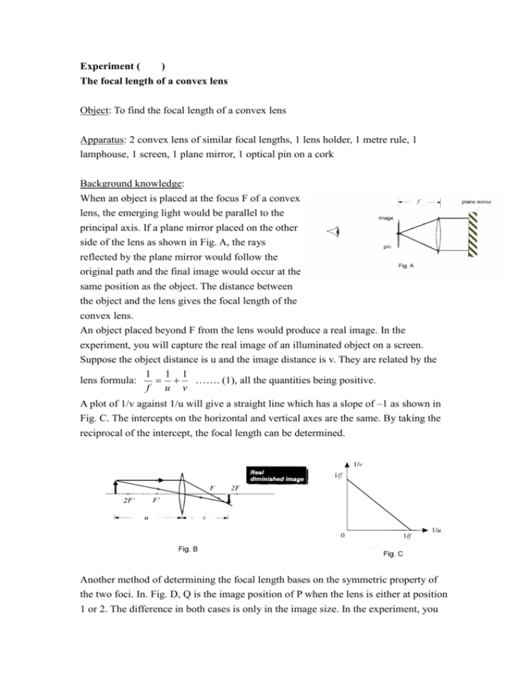
Experiment ( ) The focal length of a convex lens Object: To find the focal length of a convex lens Apparatus: 2 convex lens of similar focal lengths, 1 lens holder, 1 metre rule, 1 lamphouse, 1 screen, 1 plane mirror, 1 optical pin on a cork Background knowledge: When an object is placed at the focus F of a convex lens, the emerging light would be parallel to the principal axis. If a plane mirror placed on the other side of the lens as shown in Fig. A, the rays reflected by the plane mirror would follow the original path and the final image would occur at the same position as the object. The distance between the object and the lens gives the focal length of the convex lens. An object placed beyond F from the lens would produce a real image. In the experiment, you will capture the real image of an illuminated object on a screen. Suppose the object distance is u and the image distance is v. They are related by the 1 1 1 lens formula: ……. (1), all the quantities being positive. f u v A plot of 1/v against 1/u will give a straight line which has a slope of –1 as shown in Fig. C. The intercepts on the horizontal and vertical axes are the same. By taking the reciprocal of the intercept, the focal length can be determined. Another method of determining the focal length bases on the symmetric property of the two foci. In. Fig. D, Q is the image position of P when the lens is either at position 1 or 2. The difference in both cases is only in the image size. In the experiment, you will capture a sharp image at Q when the lens is located at position 1. The lens is moved towards the screen until another sharp image is captured again. The displacement of the lens (a) and the separation between the object and the screen (d) are measured. The object distance when the lens is at position 1 is u while the image distance is v d u 1 (d a ) , 2 1 (d a ) . Putting into equation (1), we have 2 1 1 1 . Hence, d2 – a2 = 4fd ……(2). A graph of d2 – a2 against d 1 1 f (d a) (d a) 2 2 should give a straight line as shown in fig. E. The focal length of the lens can be determined from the slope of the graph. Part A: Capturing image of distant objects 1. Hold the convex lens facing distant objects (not the window frames) outside an open window. Move the screen on the other side of the lens until the images of the distant objects are focused on the screen. 2. Measure the distance between the lens and the screen. This gives the focal length f of the lens. Part B: Locating the focus using no-parallax method 3. Place the optical pin close to the convex lens. Adjust the vertical position of the pin so that its tip is at the same level as the center of the lens. 4. Place the vertical plane mirror at a distance of 10 cm on the other side of the lens with the reflecting surface facing the lens. Make sure that the mirror and the lens are parallel. 5. Move the pin away from the lens along the principal axis until the separation is about the focal length. Adjust the position of the pin until it coincides exactly with its image. In this case, when you move your head sideways, there is no relative motion between the image and the object pin i.e. they do not separate. 6. The pin is now at the focus of the lens. Measure the focal length of the lens. 7. Move the plane mirror to vary the separation between the mirror and the lens. What happens to the image? Part C: Graphical method using an illuminated object 8. Place the lamphouse beginning with an object distance greater than twice the focal length (beyond 2F) of the convex lens. Adjust the position of the screen on the opposite side so that a sharp diminished image is formed. Measure the object distance u and the image distance v. Record your results in the Table 1: u( ) v( ) 1/u ( ) 1/v ( ) Table 1 9. Repeat step 8 to capture 3 other diminished images and 4 other magnified images on the screen. In each case, record the object distance u and the image distance v in Table 1. 10. Plot a graph of 1/v against 1/u. Draw the best-fit straight line and produce it to intersect both axes. 11. Find the intercepts on both axes. Calculate the mean intercept. Hence, determine the focal length of the convex lens. Part D: Measuring focal length by the lens displacement method using conjugate foci 12. Arrange the lamphouse and the convex lens so that a magnified sharp image is formed on the screen. 13. Place the metre rule alongside the lens and parallel to the principal axis of the lens. Record the position of the lens. 14. Move the lens towards the screen until a diminished sharp image is formed on the screen. Do not change the positions of the lamphouse or the screen. Measure the displacement (a) of the lens and the distance of separation between the object and the image (d). Record your results in Table 2: d( ) a( ) d2 – a2 ( ) Table 2 15. Change the separation between the lamphouse and the screen and repeat the experiment for at least five other times. 16. Complete Table 2. Plot a graph of d2 – a2 against d. Draw the best-fit straight line and measure the slope of the graph. Using equation (2), determine the focal length of the convex lens. Discussion: 1. All the above experiments are to find the focal length of a convex lens. Compare the reliability of the results. 2. How does the focal length change when two convex lenses of the similar focal length are placed together as shown in Fig. F? Test your answer by measuring the resulting focal length using any two of the above methods. State the difficulties you have encountered in carrying out this experiment. f1 f2 Fig. F
