Lab7_StaticEquilibrium
advertisement
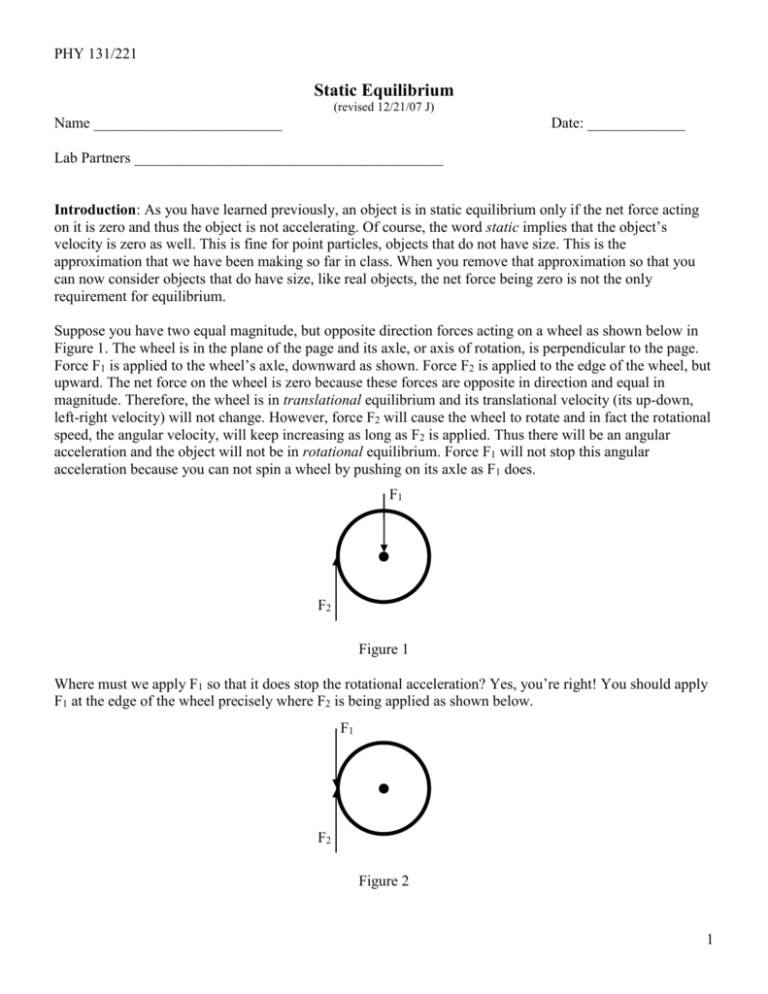
PHY 131/221 Static Equilibrium (revised 12/21/07 J) Name _________________________ Date: _____________ Lab Partners _________________________________________ Introduction: As you have learned previously, an object is in static equilibrium only if the net force acting on it is zero and thus the object is not accelerating. Of course, the word static implies that the object’s velocity is zero as well. This is fine for point particles, objects that do not have size. This is the approximation that we have been making so far in class. When you remove that approximation so that you can now consider objects that do have size, like real objects, the net force being zero is not the only requirement for equilibrium. Suppose you have two equal magnitude, but opposite direction forces acting on a wheel as shown below in Figure 1. The wheel is in the plane of the page and its axle, or axis of rotation, is perpendicular to the page. Force F1 is applied to the wheel’s axle, downward as shown. Force F2 is applied to the edge of the wheel, but upward. The net force on the wheel is zero because these forces are opposite in direction and equal in magnitude. Therefore, the wheel is in translational equilibrium and its translational velocity (its up-down, left-right velocity) will not change. However, force F2 will cause the wheel to rotate and in fact the rotational speed, the angular velocity, will keep increasing as long as F2 is applied. Thus there will be an angular acceleration and the object will not be in rotational equilibrium. Force F1 will not stop this angular acceleration because you can not spin a wheel by pushing on its axle as F1 does. F1 F2 Figure 1 Where must we apply F1 so that it does stop the rotational acceleration? Yes, you’re right! You should apply F1 at the edge of the wheel precisely where F2 is being applied as shown below. F1 F2 Figure 2 1 A force that causes rotational acceleration creates a torque on the wheel. We use the Greek letter to represent torque. The amount of angular acceleration created depends on the amount of torque that the force provides. The torque depends not only on the strength of the applied force, but also its orientation and distance from the axis of rotation. Consider the oblong shaped object in Figure 3. The actual point on an object where a force acts is called the force’s point of application. A line drawn in the direction the force is pointing, and passing through the point of application, is called the line of action. Finally, a line drawn from the axis of rotation to the line of action, and perpendicular to it, is called the lever arm, or moment arm, of the force. The vector r is a position vector for the point of application of the force assuming that the origin of the coordinate system is at the object’s axis. The moment arm, d, is equal to the magnitude of the position vector r only when the position vector r and the force F are perpendicular to one another. Line of Action d r F axis Figure 3 The magnitude of the torque created by a force equals the magnitude of the force multiplied by the length of the lever arm, d, or = d F. For the wheel in Figure 1 the lever arm for F2 is equal to the radius of the wheel, while the lever arm for F1 is zero. Why? Furthermore, torque is a vector and so we can specify its direction. (Torque is actually something called a pseudo vector, but don’t worry about that right now.) For now we will simply specify the direction by saying which direction the torque would rotate the object if it could. The directions will always be either clockwise (cw) or counter-clockwise (ccw). Finally, for an object to be in equilibrium not only must the net force on the object be equal to zero, but the net torque must also be zero. In other words, the net clockwise torque, cw, must equal the net counterclockwise torque, ccw. An example will help. Consider the meter stick in Figure 4 set to balance on a pivot, or fulcrum. Where would you place the fulcrum so that the meter stick balanced? Yes, you are correct again! You would place it at the 50 cm mark (assuming that the meter stick has a uniform mass density throughout). We would put the fulcrum at the 50 cm mark because this is where the center of gravity is. Think of the center of gravity as the balancing point of an object. Figure 4 2 Why does the stick balance when the fulcrum is at the center of gravity? Consider the meter stick being made up of a bunch of thin slices each of mass m as in Figure 5. The force of gravity on each thin slice is pointing downward and is applied at a point some distance away from the axis of rotation (the fulcrum). Thus each slice has a torque acting on it. If the axis of rotation is placed at the center of gravity then all of the torques due to gravity total zero. In other words, the net clockwise torque equals the net counter-clockwise torque. For the meter stick this is easy to understand. The slice at the 0 cm and 100 cm marks have equal, but opposite torques on them since they are equal distances from the fulcrum. Similarly the torques are equal and opposite for slices at the 1 cm and 99 cm marks, the 2 cm and 98 cm marks, etc. r mg Figure 5 In this lab you will hang weights from various positions on the meter stick so that the stick is in static equilibrium. You will need to determine how much weight and where it must be placed so that the total torque on the meter stick is zero. Part I: Fulcrum at Center of Gravity of Meter Stick: Record the mass, M, of your meter stick in the data section. You will be hanging weights from various positions on the meter stick. One way to do this is to use metal weight hanger clamps that slide over the meter stick. Grab three of these (be sure that they are identical in appearance) and weigh the bunch. Divide this weight by the number of clamps you have weighed to determine the average weight of each. Enter this in the data section. One of the weight hanger clamps can be used as a pivot support for the meter stick if you remove the hanger part and slide the clamp part onto the meter stick with the screw facing down. Position the clamp so that the meter stick balances on the support provided. Record the distance of the center of the clamp from the zero end of the meter stick. We’ll call this distance x0. i) Hang a 100 g mass from the 20 cm position of the meter stick. Let x1 = 20 cm. Be sure to weigh the mass and include the mass of the weight hanger and the average mass of one clamp. Call the total mass m1 (similarly for all masses you hang, mi will be the hanging mass plus the weight hanger plus the average mass of one clamp). The moment arm of this mass is the distance from x0 to x1; call this r1 and record in the data section. Calculate and record the torque created by mass m1. Now hang a 200 g mass from the meter stick such that the meter stick balances. The torque from the second mass now cancels out the torque from mass 1. Record the total mass, m2, its position x2, its moment arm r2 and its torque 2. Compare torques 1 and 2 by computing a percent difference. ii) Hang 100 g from 25 cm and hang 200 g from 80 cm. Calculate moment arms and torques for these masses. Calculate where a third mass, m3, of 75 g (plus hanger mass and clamp mass) should be placed to bring the system into equilibrium. Use the measured mass of m3 in your calculations. Now experimentally determine where m3 should be placed and record your measured moment arm in the data section. Also compute the percent difference between the calculated moment arm and the measured moment arm. iii) Remove all masses from the meter stick. Hang an unknown mass, m1, from the 20 cm position. Position a 100 g mass, m2, so that the system is balanced. Compute the mass of the unknown by using the 3 fact that the system is in equilibrium. Show all necessary data and calculations in the data section. Weigh the unknown mass and compare with the calculated value. Part II: Fulcrum Not At The Center Of The Meter Stick: Now remove all masses from the meter stick and move the pivot clamp to the 30 cm position. This will be your new x’0 (which you will adjust shortly). Clearly, the meter stick is unbalanced without any masses hanging from it. There are two ways to understand this: a) We can consider the total gravitational force on the meter stick, Mg, to be acting at the stick’s center of gravity, x0. This force results in an unbalanced torque. The force’s moment arm is (x0 – x’0) and so the torque it creates is (x0 – x’0) Mg. x’0 x0 Mg Figure 6 or (for PHY 221) b) We can consider the stick to be made up of two pieces, one to the left of x’0 of length L1 and the other to the right of x’0 of length L2. The segment on the left has a mass m1 and a center of gravity at x1 (somewhere between 0 cm and x’0). The segment on the right has mass m2 and has its center of gravity at x2 (somewhere between x’0 and 100 cm). There are now two torques that do not cancel out. 1 equals m1g multiplied by moment arm r1 and 2 equals m2g multiplied by moment arm r2. The question for you is, how do you determine m1 and m2? x1 x’0 m1 g x2 m2 g Figure 7 Now you will apply methods a) and b) (PHY 221) above to analyze the torques on a meter stick with a variety of masses hanging from it and with the fulcrum NOT at the stick’s center of gravity. i) Hang Tie a piece of string around a 100 gram mass and measure its mass. Tape the string holding the mass to the zero end of the meter stick. Call this mass m and record it, and its position x, in the data section. Now adjust the position of the pivot clamp, at x’0, so that the stick is balanced. Record the value for the new x’0 and compute the moment arm, r, of the hanging mass. Now that the system is balanced, the pivot point is now at the center of gravity of the system and all torques add up to zero. Show this by calculating the various torques using the two methods in a) and b) (PHY 221) above. See the data section for the appropriate data that needs to be measured and calculated. ii) With the meter stick set up as in part II(i) with a 100 g mass close to the zero position, add another 100 g mass to the 60 cm position. Adjust the pivot clamp to balance the system. The new location, x’0, of the pivot clamp is the system’s new center of gravity. Record this new x’0 in the data section. Move the 100 g 4 mass to the 70 cm mark, readjust the pivot clamp and record the new center of gravity. Repeat by moving the 100 g mass to the 80 cm position and then the 90 cm position. Proceed to the Questions section. 5 Data Mass of Meter Stick, M = ____________________(kg) Average Mass of Metal Weight Hangers = ________________(kg) Part I: x0 = ________________(m) i) Make a sketch of your setup: m1 = ___________(kg) r1 = _____________(m) 1 = ______________(N m) m2 = __________(kg) x2 = ____________(m) r2 = ______________(m) 2 = ____________(N m) percent difference between 1 and 2 = _______________ ii) Make a sketch of your setup: m1 = _________(kg) x1 = _________(m) r1 = ___________(m) 1 = ______________(N m) m2 = __________(kg) x2 = ____________(m) r2 = ____________(m) 2 = ____________(N m) m3 = ___________(kg) Calculated r3 = _____________(m) measured r3 = _________(m) measured x3 = ___________(m) Computed percent difference for r3 = _____________ 6 Show calculations for r3 below: iii) m2 = _____________(kg) x2 = ___________(m) r2 = ____________(m) Calculated m1 = ______________(kg) Measured m1 = ______________(kg) Percent Difference = ______________ Show calculations for m1 below: Part II i) m = _____________(kg) x = _____________(m) r = _____________(m) x’0 = _________________(m) Method a) Make a sketch of your setup and the relevant forces. moment arm of gravitational force on meter stick, r1 = __________(m) torque from gravitational force on meter stick. 1 = _____________(N m) torque from gravitational force on hanging mass, = ____________(N m) percent difference between torques = _______________ 7 Method b) (PHY 221) Make a sketch of your setup and the relevant forces. length of left side of meter stick, L1 = ____________(m) moment arm of gravitational force on left side of stick, r1 = ___________(m) mass of left side of meter stick, m1 = ____________(kg) length of right side of meter stick, L2 = ____________(m) moment arm of gravitational force on right side of stick, r2 = __________(m) mass of right side of meter stick, m2 = ____________(kg) total ccw torque = ___________(N m) total cw torque = ____________(N m) percent difference = ______________ ii) (Phy 131 and 221) x’0 = __________(m) for 100 g mass at 60 cm. x’0 = __________(m) for 100 g mass at 70 cm. x’0 = __________(m) for 100 g mass at 80 cm. x’0 = __________(m) for 100 g mass at 90 cm. 8 Questions 1. Suppose your unknown mass was 100 g in Part I(iii). Could you use a 50 g mass to balance the system? Explain. 2. From your data from part II(ii) can you predict where the system’s center of gravity would be located if you placed the second 100 g mass at the 50 cm mark? Explain and calculate the new center of gravity. 3. What was the greatest source of error in this experiment? Was this error random, or systematic and how do you know? 9 4. Were all of your calculated percent differences what you expected? What should they have been? Discuss any results that were not what you expected. For your lab write-up be sure to include a purpose, procedure and conclusion. Record your data in the places provided in this handout rather than in your own tables. 10
