Determination of magnetic fields outside a rectangular magnet
advertisement
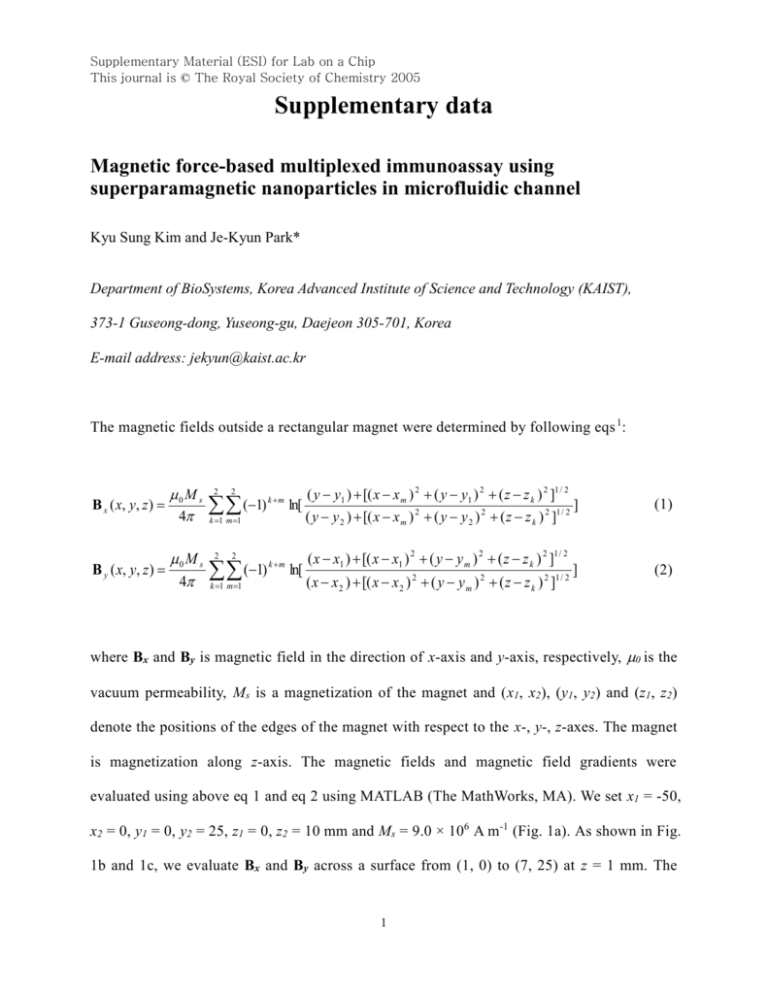
Supplementary Material (ESI) for Lab on a Chip This journal is © The Royal Society of Chemistry 2005 Supplementary data Magnetic force-based multiplexed immunoassay using superparamagnetic nanoparticles in microfluidic channel Kyu Sung Kim and Je-Kyun Park* Department of BioSystems, Korea Advanced Institute of Science and Technology (KAIST), 373-1 Guseong-dong, Yuseong-gu, Daejeon 305-701, Korea E-mail address: jekyun@kaist.ac.kr The magnetic fields outside a rectangular magnet were determined by following eqs 1: B x ( x, y, z ) 0 M s 4 M B y ( x, y, z ) 0 s 4 2 2 (1) k m ln[ k 1 m 1 2 2 (1) k 1 m 1 k m ln[ ( y y1 ) [( x x m ) 2 ( y y1 ) 2 ( z z k ) 2 ]1 / 2 ( y y 2 ) [( x x m ) 2 ( y y 2 ) 2 ( z z k ) 2 ]1 / 2 ( x x1 ) [( x x1 ) 2 ( y y m ) 2 ( z z k ) 2 ]1 / 2 ( x x 2 ) [( x x 2 ) 2 ( y y m ) 2 ( z z k ) 2 ]1 / 2 ] (1) ] (2) where Bx and By is magnetic field in the direction of x-axis and y-axis, respectively, 0 is the vacuum permeability, Ms is a magnetization of the magnet and (x1, x2), (y1, y2) and (z1, z2) denote the positions of the edges of the magnet with respect to the x-, y-, z-axes. The magnet is magnetization along z-axis. The magnetic fields and magnetic field gradients were evaluated using above eq 1 and eq 2 using MATLAB (The MathWorks, MA). We set x1 = -50, x2 = 0, y1 = 0, y2 = 25, z1 = 0, z2 = 10 mm and Ms = 9.0 × 10⁶ A m-1 (Fig. 1a). As shown in Fig. 1b and 1c, we evaluate Bx and By across a surface from (1, 0) to (7, 25) at z = 1 mm. The 1 Supplementary Material (ESI) for Lab on a Chip This journal is © The Royal Society of Chemistry 2005 magnetic fields were over 0.2 T. These values were enough to saturate magnetization of iron oxide magnetic nanoparticles. 2-4 Therefore, the velocities of microbeads conjugated with magnetic nanoparticles are proportional to the magnetic field gradient, B. The magnetic field gradients, dBx/dx at y = 10 mm and dBy/dy at x = 2 mm, were calculated. As shown in Fig. 1d and 1e, the magnetic field gradient along y-axis, dBy/dy, is much less than the magnetic field gradient along x-axis, dBx/dx. Therefore, the effect of the magnetic field gradient along y-axis, dBy/dy, could be nearly ignored. References 1 E. P. Furlani, Permanent Magnet & Electromechanical Devices: Materials, Analysis, and Applications, Academic Press, San Diego, 2001. 2 M. D. Mukadam, S. M. Yusuf, P. Sharma and S. K. Kulshreshtha, J. Magn. Magn. Mater., 2004, 272-276, 1401-1403. 3 Z. Z. Xu, C. C. Wang, W. L. Yang, Y. H. Deng and S. K. Fu, J. Magn. Magn. Mater., 2004, 277, 136-143. 4 D. K. Kim, Y. Zhang, W. Voit, K. V. Rao and M. Muhammed, J. Magn. Magn. Mater., 2001, 225, 30-36. 2 Supplementary Material (ESI) for Lab on a Chip This journal is © The Royal Society of Chemistry 2005 (a) (b) (c) (d) (e) Fig. 1 (a) Scheme of a NdFe35 permanent magnet and the location of a microfluidic device from the permanent magnet. (b) The evaluated magnetic field along x-axis by NdFe35 permanent magnet across a surface from (1, 0) to (7, 25) at z = 1 mm. The channel of microfluidic device was aligned from y = 7.5 mm to y = 12.5 mm at x = 1, 2, 3, 4, 5, 6, 7 mm and z = 1 mm. (c) The evaluated magnetic field along yaxis by NdFe35 permanent magnet across a surface from (1, 0) to (7, 25) at z = 1 mm. The channel of microfluidic device was aligned from y = 7.5 mm to y = 12.5 mm at x = 1, 2, 3, 4, 5, 6, 7 mm and z = 1 mm. (d) Calculated values of the magnetic field gradient in the x-direction, dBx/dx, at y = 10 mm and z = 1 mm. (e) Calculated values of the magnetic field gradient in the y-direction, dBy/dy, at x = 2 mm and z = 1 mm. 3
