Exercise 1 (Resistance+Propulsion)
advertisement
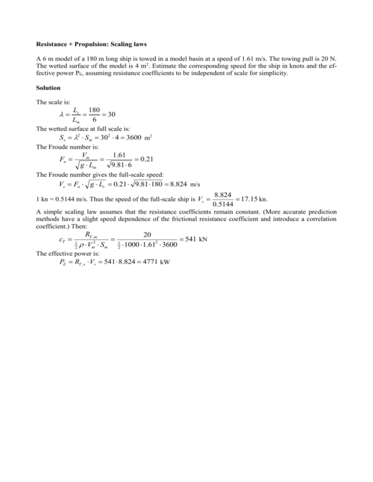
Resistance + Propulsion: Scaling laws A 6 m model of a 180 m long ship is towed in a model basin at a speed of 1.61 m/s. The towing pull is 20 N. The wetted surface of the model is 4 m2. Estimate the corresponding speed for the ship in knots and the effective power PE, assuming resistance coefficients to be independent of scale for simplicity. Solution The scale is: Ls 180 30 Lm 6 The wetted surface at full scale is: S s 2 S m 302 4 3600 m2 The Froude number is: Vm 1.61 0.21 g Lm 9.81 6 Fn The Froude number gives the full-scale speed: Vs Fn g Ls 0.21 9.81 180 8.824 m/s 1 kn = 0.5144 m/s. Thus the speed of the full-scale ship is Vs 8.824 17.15 kn. 0.5144 A simple scaling law assumes that the resistance coefficients remain constant. (More accurate prediction methods have a slight speed dependence of the frictional resistance coefficient and introduce a correlation coefficient.) Then: cT 1 2 RT , m 20 1 541 kN 2 Vm Sm 2 1000 1.612 3600 The effective power is: PE RT , s Vs 541 8.824 4771 kW Resistance + Propulsion: Simple scaling laws a) A ship of 15000 t displacement has speed 20 kn. Determine the corresponding speed for a similar ship of displacement 14000 t using geometric and Froude similarity. b) A ship of 140 m length has speed 15 kn. Determine the corresponding speed for a 7 m model. c) A ship of 5000 t displacement has speed 18 kn, length 120 m. The towing tank model has 6 m length. At which speed should the model be tested? What is the ratio of the ship-to-model PE at this speed? Solution a) Let's denote the ship with 15000 t displacement with index 1, the other with index 2. The lengths L of the ships correlate to the displacements following geometric similarity: L13 1 L32 2 L1 L2 3 1 3 2 The speeds follow from Froude similarity: V1 gL1 V2 gL2 L V2 V1 2 V1 2 L1 1 1/ 6 14000 20 15000 1/ 6 19.8 kn b) We keep Froude similarity: Vm V s gLm gLs Vm Vs Lm 7 15 3.35 kn = 1.73 m/s Ls 140 c) We keep Froude similarity: Vm V s gLm gLs Vm Vs Lm 6 18 4.02 kn = 2.07 m/s Ls 120 The effective power follows from PE = RV. The resistance is expressed as R c 12 V 2 A ; thus it scales with 3, as the area scales with 2 and the speed in Froude similarity scales with 0.5. Thus the power scales with 3.5: PE , s Ls PE , m Lm 3.5 120 6 3.5 35777 Resistance + Propulsion: Power estimate following simple scaling laws A ship (L = 122.00 m, B = 19.80 m, T = 7.33 m, = 8700 t) has the following power requirements: V [kn] 16 17 18 19 20 P [kW] 2420 3010 3740 4620 5710 Estimate the power requirements for a similar ship with 16250 t displacement at speed 19.5 knots. Solution We convert the speed of the new ship of 19.5 kn to the corresponding speed for the original ship, following Froude and geometric similarity: 1/ 6 V1 V2 V2 1 gL2 2 gL1 8700 19.5 16250 1/ 6 17.57 kn For this speed, the power for the original ship is linearly interpolated to: P1 (17.57 17) 3740 3010 3010 3426 kW 18 17 This is scaled to the new ship: P P1 new old 3.5 / 3 16250 3426 8700 3.5 / 3 7088 kW Explanation: Power scales with speed V3 and area A, which gives for the speed with Froude similarity a scale with length scale 1.5 and for the area 2, thus together 3.5. If we use the displacement instead of the length, we divide by 3. Hence the exponent of 3.5/3. Resistance + Propulsion: Ship vs Car - Scaling and resistance prediction A car has a wind resistance value of CW = 0.3. The car has a frontal area of 2 m2. The air density is 1.23 kg/m3 and the car weighs 1200 kg. Now compare the efficiency of a ship to that of the car. A ferry has a resistance of 2000 kN at a speed of 25 kn. The ferry has a mass of 16500 t, length Lpp = 190 m, and a wetted surface of 4400 m2. a) b) c) d) e) Compute the necessary power for car speeds of 10, 20, 30, 40, 100 and 200 km/h. What scale has to be taken to get a ship model of same mass as the car? What is the model speed if Froude similarity is kept? What is the model resistance if the correlation allowance is cA = 0? How fast could the car go with the same power the ship model needs in towing at design Froude number? sea = 1.1610-6 m2/s, fresh = 1.1410-6 m2/s, sea = 1026 kg/m3 Solution a) The force follows from: F CW air 2 V 2 A The reference area is here the frontal area. Thus: V 10 km/h 20 km/h 30 km/h 40 km/h 100 km/h 200 km/h F 2.85 N 11.39 N 25.63 N 45.60 N 284.72 N 1138.9 N 2.78 m/s 5.56 m/s 8.3 m/s 11.11 m/s 27.78 m/s 55.60 m/s P = FV 8W 63 W 212 W 506 W 7910 W 63272 W b) Geometric similarity gives: 1/ 3 s m 1/ 3 16500 1.2 23.957 Then the model length is: Lm Ls 190 7.93 m 23.957 c) The ship speed is: Vs 25 0.5144 12.861 m/s The Froude number of the ship is: Vs 12.861 0.298 gLs 9.81 190 Fn Model and full-scale ship have the same Froude number, thus: Vm Fn gLm 0.298 9.81 7.93 2.63 m/s d) First, we compute the Reynolds numbers of ship and model: 12.861 190 21 108 6 sea 1.16 10 V L 2.63 7.93 m m 18.3 106 fresh 1.14 10 6 Rn , s Rn, m Vs Ls The frictional resistance coefficients are: 0.075 0.075 1.398 10 3 2 2 8 log 10 Rn, s 2 log 10 21 10 2 0.075 0.075 2.708 10 3 2 2 6 log 10 Rn,m 2 log 10 18.3 10 2 cF , s cF , m The total resistance coefficient for the ship is: cT , s RT , s 2 106 5.357 10 3 2 2 1 1 V S 1026 12.86 4400 2 sea s s 2 We assume the same wave resistance coefficient for full scale and model scale. Thus: cT , m cF , m cF , s cT , s (2.708 1.398 5.357) 103 6.676 103 This yields a resistance (with S m S s / 2 ): RT ,m cT ,m m 2 Vm2 Ss 2 6.676 10 3 1000 4400 2.632 177 kN 2 23.957 2 e) The necessary power to tow the model: P RT , m Vm 177 2.63 465.5 W For the car we have: P CW air 2 V 3 Am V 3 P 465.5 3 10.8 m/s CW air A 0.3 12 1.23 2 1 2 = 38.9 km/h Resistance + Propulsion: Sailing yacht test A sailing yacht has been tested. The full-scale dimensions are Lpp = 9.00 m, S = 24.0 m2, = 5.150 m3. The yacht will operate in sea water of = 1025 kg/m3, = 1.19106 m2/s. The model was tested with scale = 7.5 in fresh water with = 1000 kg/m3, = 1.145106 m2/s. The experiments yield for the model: Vm [m/s] 0.5 0.6 0.75 0.85 1.0 1.1 1.2 RT,m [N] 0.402 0.564 0.867 1.114 1.584 2.054 2.751 a) Determine the form factor following Hughes-Prohaska. b) Determine the form factor following ITTC'78. For simplification assume the exponent n for Fn to be 4 and determine just and k in regression analysis. Solution The model data are: Lm = Ls/ = 9/7.5 = 1.2 m Sm = Ss/2 = 24/7.52 = 0.427 m2 We consider only the lowest 4 speeds as for the others a considerable wave influence is to be expected. a) We compute the total resistance coefficient of the model, using Fn V / gL , Rn V L / , cF ,0 0.067 /(log 10 Rn 2)2 Vm 0.50 m/s 0.60 m/s 0.75 m/s 0.85 m/s RT,m 0.402 0.564 0.867 1.114 Fn Rn105 cF0 103 cT 103 0.146 5.24 4.843 7.532 0.175 6.29 4.643 7.338 0.219 7.86 4.415 7.219 0.248 8.91 4.295 7.222 cT/cF0 Fn4/cF0 1.555 0.091 1.580 0.197 1.635 0.507 1.681 0.859 Then regression analysis (e.g. using a spreadsheet like Excel) yields = 0.165 and k = 0.545. (If only the last 3 points are used, = 0.190, k = 0.540.) b) We compute now: cF 0.075 /(log 10 Rn 2) 2 Vm 0.50 0.60 0.75 0.85 RT,m 0.402 0.564 0.867 1.114 Fn Rn105 cF 103 cT 103 0.146 5.24 5.422 7.532 0.175 6.29 5.198 7.338 0.219 7.86 4.943 7.219 0.248 8.91 4.807 7.222 cT/cF 1.389 1.412 1.461 1.502 Fn4/cF 0.082 0.176 0.453 0.768 The expression for n = 4 is: cT Fn4 (1 k ) cF cF Regression analysis yields = 0.189 and k = 0.376. The form factor differs from Hughes-Prohaska, as the ITTC'57 line considers already to some extent a form influence. Resistance & Propulsion: ITTC’78 for underwater vehicle An underwater vehicle shall be tested to make a resistance prediction. The streamlined body is tested in a wind tunnel. The following data are given: Sm = 1.2 m2, Lm = 1.5 m, Vm = 30 m/s, T = 25°C. The density and viscosity of air at standard atmospheric pressure are (as function of temperature): 1.293 273 kg/m3 T 273 = 105(1.723+0.0047T) kg/(ms) where T is the temperature in °C. The model resistance measured in the wind tunnel is 3.9 N. The full-scale vehicle is 9 m long and operated in the ocean at 15°C, = 1.19106 m2/s, = 1026 kg/m3. a) What similarity law is most important and what full-scale speed in m/s corresponds to keeping this law? b) What is the full-scale resistance at this speed (using same total resistance coefficient)? c) Predict the full-scale resistance following ITTC'78 assuming cAA = cA = 0 for full-scale speed 2 m/s? d) Can the accuracy of prediction be improved by changing the temperature in the wind tunnel? How? Solution a) For an underwater vehicle, wave resistance (and thus Froude similarity) can be neglected. Thus Reynolds similarity is most important. Same Reynolds number then yields the full-scale speed: 273 273 1.293 1.1845 kg/m3 T 273 25 273 m 105 1.723 0.0047 T 105 1.723 0.0047 25 105 1.8405 kg/(ms) m 1.293 m m 105 1.8405 1.5538 10 5 m2/s m 1.1845 Rn , m Vm Lm m 30 1.5 2.896 106 5 1.5538 10 Keeping Reynolds similarity (Rn,m=Rn,s) then yields: Vs Rn, s s Rn, m s 2.896 106 1.19 106 0.3829 m/s Ls Ls 9 b) The total resistance coefficient is: cT 1 2 Rm 3.9 1 6.097 10 3 2 2 Vm S m 2 1.1845 30 1.2 The wetted surface at full scale is: 2 L 9 S s S m s 1.2 43.2 m2 1.5 Lm 2 Thus the resistance at full scale (assuming same resistance coefficient) is: RT cT 2 Vs2 S s 6.097 10 3 1026 0.38292 43.2 19.8 N 2 c) The wave resistance (coefficient) is zero. Thus we have simply: cT (1 k ) cF 0.075 0.075 cF 3.767 10 3 2 2 6 log 10 Rn 2 log 10 2.896 10 2 1 k cT 6.097 103 1.6185 cF 3.767 10 3 Thus, we have the resistance at 2 m/s: 29 15.12 106 6 s 1.19 10 0.075 0.075 cF 2.795 10 3 2 2 6 log 10 Rn 2 log 10 15.12 10 2 Rn Vs Ls 3 cT (1 k ) cF 1.6185 2.795 10 4.52 103 1026 2 RT cT Vs2 S s 4.52 10 3 2 43.2 401 N 2 2 d) Reducing the temperature increases the Reynolds number. However, to get the same Reynolds number in this case would require a temperature of 163°C... Resistance & Propulsion: ITTC’57 full-scale prediction The full-scale ship is 140 m long and has speed 15 kn, the model 4.9 m. The resistance is measured to 19 N in the model basin. Following the ITTC'57 approach, what is the predicted full-scale resistance? The wetted surface of the full-scale ship is 3300 m2. The density of sea water 1025 kg/m3, that of fresh water 1000 kg/m3. m = 1.14106 m2/s , for fresh water, s = 1.19106 m2/s for sea water. Use a correlation coefficient of cA =0.0004. Solution The speed for the model follows from Froude similarity: Vm Vs Lm 4.9 15 0.5144 1.44 m/s Ls 140 The wetted surface follows from geometric similarity: S m L2m 2 Ss Ls Sm Ss L2m 4.9 2 3300 4.043 m2 2 2 Ls 140 The Reynolds numbers are: Rn,s Vm Lm 1.44 4.9 6.189 10 6 6 m 1.14 10 V L (15 0.5144) 140 s s 9.078 108 s 1.19 10 6 Rn,m This yields friction resistance coefficients following ITTC'57: c F ,m c F ,s 0.075 log 10 Rn 2 2 0.075 log 10 Rn 22 log log 0.075 10 9.078 10 2 8 10 3.267 10 3 1.549 10 3 6.189 10 2 0.075 6 2 2 The total resistance of the model follows from the model test: cT , m RT ,m 1 2 mV S m 2 m 1 2 19 4.533 10 3 2 1000 1.44 4.053 The wave resistance coefficient (assumed same for model and ship) is then: cw cT ,m cF ,m 4.533 10 3 3.267 10 3 1.266 10 3 Thus the total resistance coefficient of the ship is: cT ,s cF ,s cw c A (1.549 1.266 0.4) 10 3 3.215 10 3 The resistance follows: RT ,s cT ,s s 2 Vs2 S s 3.215 10 3 1025 7.716 2 3300 323.7 kN 2 Resistance & Propulsion: ITTC’78 full-scale prediction including appendages A ship model with scale = 23 was tested in the model basin with 104.1 N total resistance for the bare hull model at towing speed Vm = 2.064 m/s. The wetted surface of the model is Sm = 10.671 m2 and its length Lm = 7.187 m. The viscosity is = 1.14106 m2/s in fresh water and = 1.19106 m2/s in sea water, density = 1000 kg/m3 in fresh water, 1025 kg/m3 in sea water. a) What is the prediction for the total calm-water resistance of the bare hull in sea water of the fullscale ship following ITTC'78 with a form factor k = 0.12? Assume standard roughness ks/Loss = 106, corresponding roughly to 150 m average surface roughness, neglect air resistance. b) The appendages of the ship (bilge keels, shaft brackets and rudder) add 8% to the total resistance of the smooth bare hull. What is the total resistance now? c) Fouling increases the surface roughness by a factor 10 to ks/Loss = 105. What is the total resistance now? Solution The full-scale ship data are: Ls Lm 23 7.187 165.30 m Vs Vm 23 2.064 9.899 m/s S s 2 S m 232 10.761 5645 m2 The Reynolds numbers for model and full scale are: 2.064 7.187 1.301 107 m 1.14 10 6 V L 9.899 165.3 s s 1.375 109 6 s 1.19 10 Rn , m Rn , s Vm Lm The friction coefficients follow: 0.075 0.075 2.867 10 3 2 2 7 log 10 Rn 2 log 10 1.301 10 2 0.075 0.075 1.472 10 3 2 2 9 log 10 Rn 2 log 10 1.375 10 2 cF , m cF , s The frictional resistance for model and full scale follow: RF , s m 1000 2.064 2 10.671 65.2 N 2 2 1025 cF , s s Vs2 S s 1.472 10 3 9.8992 5645 417.2 kN 2 2 RF , m c F , m Vm2 S m 2.867 10 3 a) We compute the correlation coefficient following ITTC’78: k c A 10 3 105 3 s 0.64 10 3 105 3 10 6 0.64 0.41 10 3 Loss The total resistance coefficient of the model and the model is: cT , m 1 2 RT , m 104.1 1 4.580 103 2 2 mVm Sm 2 1000 2.064 10.671 The total resistance coefficient of the full-scale ship follows then according ITTC'78: cT , s (1 k )(cF , s cF , m ) cT , m cA (1 0.12)(1.472 2.867) 4.580 0.41 3.427 103 RT ,s cT ,s s 2 Vs2 S s 3.427 10 3 1025 9.899 2 5645 971.4 kN 2 b) We add 8% for the appendages: RT ,incl appendages 1.08 RT , s 1.08 971.4 1049 kN c) The fouling changes the correlation coefficient: k c A 10 3 105 3 s 0.64 10 3 105 3 10 5 0.64 1.622 10 3 Loss cT ,s (1 k )(cF ,s cF ,m ) cT ,m c A (1 0.12)(1.472 2.867) 4.580 1.622 4.639 10 3 RT ,s cT ,s s 2 Vs2 S s 4.640 10 3 1025 9.899 2 5645 1315 kN 2 This represents an increase of 35% in total bare hull resistance. Resistance + Propulsion: ITTC'57 and ITTC'78 A ship model (scale = 23) was tested in fresh water with: RT,m = 104.1 N, Vm = 2.064 m/s, Sm = 10.671 m2, Lm = 7.187 m. m = 1000 kg/m3, s = 1026 kg/m3, m = 1.14 106 m2/s, s = 1.19 106 m2/s What is the prediction for the total calm-water resistance in sea water of the full-scale ship following ITTC'57? Assume cA = 0.0002. Solution The full-scale ship data are: Ls Lm 23 7.187 165.3 m Vs Vm 23 2.064 9.899 m/s Thus: S s 2 S m 232 10.761 5645 m2 V L 2.064 7.187 Rn , m m m 1.301 107 m 1.14 10 6 V L 9.899 165.3 Rn , s s s 1.375 109 6 s 1.19 10 0.075 0.075 cF , m 2.867 10 3 2 2 7 log 10 Rn,m 2 log 10 1.301 10 2 0.075 0.075 1.472 10 3 2 2 9 log 10 Rn, s 2 log 10 1.375 10 2 1000 RF , m cF , m m Vm2 S m 2.867 10 3 2.0642 10.671 65.1 N 2 2 1026 RF , s cF , s s Vs2 S s 1.472 10 3 9.8992 5645 417.7 kN 2 2 cF , s Residual resistance: RR RT RF . Thus RR , m RT , m RF , m 104.1 65.1 39 N. Residual resistance coefficient: cR, m 1 2 RR, m 39 1 1.718 103 2 2 m Vm Sm 2 1000 2.064 10.671 The residual resistance coefficient is assumed to be constant. Then: RR , s cR , s s 2 1026 9.8992 5645 487.5 kN 2 cF , s cR, m cA (1.472 1.718 0.2) 103 3.390 103 Vs2 S s 1.78 10 3 Total resistance coefficient: cT , s Total calm-water resistance at full scale: RT , s cT , s s 2 Vs2 S s 3.390 10 3 1026 9.8992 5645 962.9 kN 2 Resistance + Propulsion: Power scaling from model to ship following ITTC'57 A model of 6 m length has total resistance 70 N at 1.8 m/s. The wetted surface of the model is 5 m2. Determine the resistance for a geometrically similar ship of length 130 m using the ITTC'57 approach. Density of model basin water m = 1000 kg/m3, density of sea water s = 1026 kg/m3. m = 1.14 106 m2/s for fresh water, s = 1.19 106 m2/s for sea water. Use a correlation coefficient cA = 0.00035. Solution The speed for the ship follows from Froude similarity: Vs Vm Ls 130 1.8 8.38 m/s = 16.3 kn Lm 6 The wetted surface follows from geometric similarity: S s Ls S m Lm 2 L S s S m s Lm 2 130 5 2347 m2 6 2 The Reynolds numbers are: 1.8 6 9.47 106 m 1.14 10 6 V L 8.38 130 s s 9.15 108 6 s 1.19 10 Rn , m Rn , s Vm Lm This yields friction resistance coefficients following ITTC'57: 0.075 0.075 3.028 10 3 2 2 6 log 10 Rn,m 2 log 10 9.47 10 2 0.075 0.075 1.548 10 3 2 2 8 log 10 Rn, s 2 log 10 9.15 10 2 cF , m cF , s The total resistance coefficient of the model follows from the model test: cT , m 1 2 RT , m 70 1 8.642 103 2 2 mVm Sm 2 1000 1.8 5 The wave resistance coefficient (assumed same for model and ship) is then: cw cT , m cF , m (8.642 3.028) 103 5.614 103 Thus the total resistance coefficient of the ship is: cT , s cF , s cw cA (1.548 5.614 0.35) 103 7.511 103 The resistance follows: RT , s cT , s s 2 Vs2 S s 7.511 10 3 1026 8.382 2347 635.1 kN 2 Resistance + Propulsion: Resistance prediction with base design following ITTC'57 A base ship (Index O) has the following main dimensions: Lpp,O = 128.0 m, BO = 25.6 m, TO = 8.53 m, CB = 0.565. At a speed VO = 17 kn, the ship has a total calm-water resistance of RT,O = 460 kN. The viscosity of water is = 1.19 106 m2/s and density = 1026 kg/m3. What is the resistance of the ship with Lpp = 150 m if the ship is geometrically and dynamically similar to the base ship and the approach of ITTC'57 is used (essentially resistance decomposition following Froude's approach)? The wetted surface may be estimated by an empirical estimate: S 3.4 1 / 3 0.5 Lwl 1 / 3 Lwl may be estimated by Lwl = 1.01Lpp. The Reynolds number shall be based on Lpp. The correlation coefficient can be neglected. Solution The ships are geometrically similar with scaling factor: We have: Lpp,1 Lpp,O 150 1.1719 128 O CB ,O L pp,O BO TO 0.565 128 25.6 8.53 15792.4 m3 Lwl ,O 1.01 L pp, O 1.01 128 129.28 m. SO 3.4 1 / 3 0.5 Lwl 1 / 3 3.4 15792.41 / 3 0.5 129.28 15792.41 / 3 m2 S1 SO 1.1719 3761.9 5166.4 m 2 2 2 The speed of the base ship is VO = 17 kn = 170.5144 = 8.7448 m/s. Dynamic similarity means: V1 VO 1.1719 8.7448 9.467 m/s Then we have: VO Lpp,O 8.7448 128 9.406 108 6 1.19 10 V1 Lpp,1 9.467 150 Rn,1 1.193 109 6 1.19 10 0.075 0.075 cF , O 1.5423 10 3 2 2 8 log 10 Rn,O 2 log 10 9.406 10 2 Rn,O 0.075 0.075 1.4976 10 3 2 2 9 log 10 Rn,1 2 log 10 1.193 10 2 1026 RF ,O cF ,O VO2 SO 1.5423 10 3 8.74482 3761.9 227.6 kN 2 2 1026 RF ,1 cF ,1 V12 S1 1.4976 10 3 9.467 2 5166.4 355.7 kN 2 2 The residual resistance is RR RT RF . Thus: RR ,O RT ,O RF ,O 460 227.6 232.4 kN cF ,1 Then: RR,1 RR,O 3 232.4 1.17193 374.0 kN and RT ,1 RR ,1 RF ,1 374.0 355.7 729.7 kN Resistance & Propulsion: Ship-propeller interaction based on model test Consider the propeller and ship described below: s f W D J n KT V R 0 density of sea water kinematic viscosity of sea water kinematic viscosity of fresh water wake fraction propeller diameter advance number (open-water) propeller rpm thrust coefficient ship speed relative rotative efficiency open-water efficiency 1026 1.13910-6 1.18810-6 0.135 4.5 0.833 3 0.1594 13 0.95 0.684 kg/m3 m/s2 m/s2 m 1/s m/s a) The ship resistance at design speed is 580 kN. The ship is at constant speed. What is the thrust deduction fraction t? b) Give an estimate for the propulsive efficiency D. c) For a 1:16 model of the ship a wake fraction w = 0.19 is measured in towing tank tests. What should be the propeller rpm at the model speed corresponding to full-scale design speed? d) Compare Reynolds numbers at 0.7R for the model and at full scale. The full-scale propeller chord c at r/R = 0.7 is 2 m. Solution a) The propeller thrust follows from: T K T n 2 D 4 0.1594 1026 32 4.5 4 603.5 kN Thrust and resistance (without propeller) are coupled by: T (1 t ) RT t 1 RT 580 1 0.04 T 603.5 The thrust deduction is thus 4%. b) Inflow velocity: V A Vs (1 w) 13 (1 0.135) 11.245 m/s RT Vs 580 13 1.111 T VA 603.5 11.245 Propulsive efficiency: D 0 R H 0.684 0.95 1.111 0.72 Hull efficiency: H c) Similarity laws give: Vs Vm Inflow velocity in model scale: VA,m Vs 13 3.25 m/s 16 Vm (1 wm ) 3.25 (1 0.19) 2.63 m/s Vm The advance number in model scale is equal to the advance number in full scale. This gives: n V A, m J Dm V A, m J ( Ds / ) 2.63 11.2 Hz 0.833 (4.5 / 16) Thus the model propeller turns at 674 rpm. 2 2 d) Circumferential velocity at r/R=0.7: VR V A (0.7nD ) At full scale: VR,s 11.245 2 (0.7 3 4.5) 2 31.75 m/s 2.632 (0.7 11.2 (4.5 / 16)) 2 7.4 m/s At model scale: VR ,m Reynolds number: Rn At full scale: Rn , s VR c VR , s c s At model scale: Rn ,m s VR ,m c m m 31.75 2 56 10 6 6 1.139 10 7.4 (2 / 16) 0.78 10 6 6 1.188 10 The model scale Reynolds number is close to the point where laminar/turbulent transition is expected. Unless turbulence is stimulated, some contamination due to partially laminar flow may be expected. Resistance + Propulsion: Resistance prediction with model tests Make a resistance prognosis for a newly designed containership. A model of the ship is towed in a model basin. Temperature of seawater shall be 15°, its salinity 3.5%, temperature of water in basin 20°. The model basin measures the values given in the table below. V [kn] 2.4 2.6 2.8 2.9 3.0 3.1 3.2 3.3 3.4 R [N] 23.24 28.38 33.92 37.53 41.47 44.79 47.49 52.13 58.71 The model has Lpp = 5.6 m at model scale = 25 and wetted surface S = 8.16 m2. a) Compute density, viscosity and wetted surface for model and full scale, using the formulae: 106 0.014 s (0.000645 t 0.0503) t 1.75 p1 p2 0.7028423 p1 p1 = 5884.8170366 + t(39.803732+t(-0.3191477+t0.0004291133)) + 26.126277s p2 = 1747.4508988 + t(11.51588 0.046331033t) s(38.5429655+0.1353985t)) where s is the salinity and t the temperature in °C. b) Compute Froude and Reynolds numbers for the model test, the speeds and Reynolds numbers for full scale. c) Compute the frictional (ITTC'57), residual and total resistance coefficients for the model. d) Compute the frictional and total resistance coefficients for full scale as well as the resistance at full scale following ITTC'57, assuming cA = 0.0003. Solution a) Using Ls Lm , S s 2 S m and the formulas with s = 0.035 and t = 20, we get: Model Full scale Lpp [m] 5.6 140 S [m2] 8.16 5100 0.9983 1.026 [t/m3] 2 6 [m /s] 1.00210 1.190106 b) Fn V L V and Rn and 1 kn = 0.5144 m/s. Then we have: gL pp Vm [kn] Vm [m/s] 2.4 1.235 2.6 1.337 2.8 1.440 2.9 1.492 3.0 1.543 3.1 1.595 3.2 1.646 3.3 1.698 3.4 1.749 Fn Rn,m106 0.1666 6.900 0.1804 7.475 0.1943 8.050 0.2013 8.337 0.2082 8.625 0.2151 8.912 0.2221 9.200 0.2290 9.487 0.2360 9.775 Vs [m/s] Vs [kn] Rn,s106 6.173 12.0 778.1 6.687 13.0 842.9 7.202 14.0 907.8 7.459 14.5 940.2 7.716 15.0 972.6 7.973 15.5 1005.0 8.230 16.0 1037.4 8.488 16.5 1069.9 8.745 17.0 1102.3 c) RT , m 1 Vm2 Sm 2 m 0.075 log 10 Rn, m 22 cT , m cF , m cR cT , m cF , m Vm [kn] RT [N] cT,m103 cF,m103 cR103 2.4 23.24 3.744 3.203 0.540 2.6 28.38 3.895 3.158 0.738 2.8 33.92 4.014 3.116 0.898 2.9 37.53 4.141 3.097 1.043 3.0 41.47 4.275 3.079 1.197 3.1 44.79 4.324 3.061 1.264 3.2 47.49 4.303 3.044 1.259 3.3 52.13 4.442 3.028 1.414 3.4 58.71 4.712 3.012 1.700 d) cT , s cF , s cR c A cF , s 0.075 log 10 Rn, s 22 RT , s cT , s s 2 Vs2 S s Vs [kn] 12.0 13.0 14.0 14.5 15.0 15.5 16.0 16.5 17.0 cF,s103 1.579 1.564 1.549 1.542 1.536 1.530 1.524 1.518 1.512 cT,s103 RT [kN] 2.420 242.2 2.602 304.4 2.747 372.7 2.886 420.1 3.033 472.0 3.094 514.6 3.083 546.4 3.232 609.2 3.513 702.9 Resistance + Propulsion: Wageningen propeller behind ship Consider a ship with speed Vs = 15 kn, thrust deduction fraction t = 0.2, wake fraction w = 0.15. The ship is equipped with a Wageningen B4-40 propeller with diameter D = 6 m. The water density is = 1025 kg/m3. The resistance curve between 10 and 16 kn is given in good approximation by (R in kN, V in kn): R 10 V 2 185 V 1100 a) What is the required thrust? b) At what points (J, KT, KQ, 0) does the propeller operate assuming P/D = 0.8, 0.9, 1.0, 1.1, and 1.2, respectively? c) What propeller P/D would you chose? What are the corresponding open-water efficiency, torque and delivered power of the engine? d) What are then delivered power and open-water efficiency at Vs = 12 kn? Use the file Wageningen_B4-40.pdf to find the solution. Solution a) Resistance at Vs = 15 kn: R 10 V 2 185 V 1100 10 152 185 15 1100 575 kN RT 575 718.85 kN 1 t 1 0.2 T b) The thrust coefficient is defined as: KT n2 D 4 V J A The advance number is defined as: nD The inflow velocity is: VA (1 w) Vs (1 0.15) (15 0.5144) 6.559 m/s Thrust at Vs = 15 kn: T We eliminate the unknown rpm from these two equations: KT T 718.75 0.453 KT 0.453 J 2 2 2 2 J VA D 1.025 6.5592 62 We compute a characteristics curve: J 0.55 0.60 0.65 0.70 0.75 0.80 0.85 0.90 KT 0.137 0.163 0.191 0.222 0.255 0.290 0.327 0.367 Now we plot this function in the diagram for the B4-40 propeller. The intersections of this KT = f(J) curve with the KT curves of the propeller for the various P/D values (solid lines) gives (approximately taken from the diagram) J and KT. The corresponding values of 0 and 10KQ for this J are listed as well: P/D 0.8 0.9 1.0 1.1 1.2 J 0.570 0.620 0.665 0.705 0.745 KT 0.147 0.174 0.200 0.225 0.251 10KQ 0.150 0.265 0.330 0.400 0.475 0 0.620 0.630 0.635 0.630 0.625 c) The best efficiency is for P/D = 1.0 with 0 = 0.635. So we select this propeller. The propeller rpm VA V 6.559 n A 1.64 s-1 = 98.6 rpm nD J D 0.665 6 Torque follows from: Q KQ n2 D5 0.033 1025 1.642 65 707 kNm follows from: J The necessary delivered power follows from: PD 2 n Q 2 1.64 707 7285 kW d) Correspondingly we get for 12 knots: R12 10 122 185 12 1100 320 kN R 320 T12 12 400 kN 1 t 0.8 VA (1 0.15) (12 0.5144) 5.247 m/s KT ,12 0.394 J 2 J 0.55 0.60 0.65 0.70 0.75 0.80 0.85 0.90 KT,12 0.119 0.142 0.166 0.193 0.222 0.252 0.285 0.319 P/D 1.0 J 0.690 KT 0.188 10KQ 0.405 0 0.650 VA 5.247 1.267 s-1 = 76.0 rpm J D 0.690 6 Q KQ n2 D5 0.0405 1025 1.2672 65 518 kNm This yields: n PD 2 n Q 2 1.167 518 4124 kW Resistance + Propulsion: Containership lengthened – Lap-Keller A container ship shall be lengthened by adding a parallel midship section of 12.50 m length (40' container and space between stacks). At full engine power (100% MCR = maximum continuous rating), the ship is capable of V = 15.6 kn. Ship data (original before conversion): Lpp Lwl B T = 117.20 m = 120.00 m = 20.00 m = 6.56 m rb = 1.5 m (bilge radius) CB = 0.688 lcb = 0.0 m Wake fraction and thrust deduction are estimated by: w 0.75 CB 0.24 and t 0.5 CB 0.15 Viscosity and density are: = 1.1910-6 m2/s, sea = 1025 kg/m3 The ship is equipped with a propeller with 0 = 0.55. The relative rotative efficiency is R = 1. a) What is the power requirement before conversion? b) What is the power requirement after conversion, if the propeller is assumed to remain unchanged? Base your prediction on Lap-Keller1, with correlation coefficient c A 0.35 103 . Solution a) Considerations for the original hull The displacement is: CB L pp B T 0.688 117.20 20.00 6.56 10579 m3 The wetted surface following Keller (1973) is: S (3.4 1 / 3 0.5 Lpp ) 1 / 3 (3.4 105791 / 3 0.5 117.20) 105791 / 3 2925 m2 The midship section area is: Am B T rb2 2 20.00 6.56 1.5 2 2 130.20 m2 2 2 C 0.688 A 130.20 0.9926 and CP B 0.692 . Thus Cm m B T 20 6.56 CM 0.9926 CP = 0.692 and lcb = 0 make this ship a group C ship according to Keller's (1973) Figure 1. The calculation length for Lap-Keller is Ld 1.01 L pp 1.01 117.20 118.37 m. ( Ld Lwl for Lwl 1.01L pp , but this is not the case here.) The prismatic coefficient based on this length is CPd = CP/1.01 = 0.685. The speed is V = 15.6 kn = 8.025 m/s. 8.025 118.37 7.983 108 6 1.19 10 0.075 0.075 1.574 10 3 cF following ITTC'57 is: cF 2 2 8 log 10 Rn 2 log 10 7.983 10 2 The Reynolds number is: Rn V Ld The residual coefficient is determined following Lap-Keller. For V 8.025 0.891 and CP = 0.692 we read from the diagram in Fig.4 of Keller CPd L 0.685 118.37 (1973): r = 0.025. We do not have to apply any correction for CP, as CP < 0.8. Then: 1 Lap, A.J.W. (1954). Diagrams for determining the resistance of single screw ships. Int. Shipb. Progr., p.179; Keller, W.H. auf'm (1973). Extended diagrams for determining the resistance and required power of single-screw ships. Int. Shipb. Progr., p.253 cR Am 130.20 r 0.025 1.111 10 3 S 2925 The correction factor K2 for B/T is given by Lap (1954) as: B 20.00 K 2 1 0.05 2.4 1 0.05 2.4 1.032 T 6.56 The total resistance is: RT c F c R c A K 2 2 V 2 S 1.574 1.111 0.35 1.032 1025 8.025 2 2925 2 = 302 kN PE RT V 302 8.025 2424 kW w 0.75 CB 0.24 0.75 0.688 0.24 0.276 t 0.5 CB 0.15 0.5 0.688 0.15 0.194 1 t 1 0.194 H 1.113 1 w 1 0.276 PE 2424 PD 3960 kW H 0 R 1.113 0.55 1 b) Considerations after ship conversion (We denote values for the new version by a prime.) The new length is L' pp L pp L 117.20 12.50 129.70 m. Thus L'd 1.01 L' pp 1.01 119.70 131.00 m. ' Am L 10579 130.2 12.50 12206.5 m3 12206.5 C 'B 0.710 L'B T 131 20 6.56 C' 0.710 C' C 'P B 0.715 and C 'Pd P 0.708 . 1.01 CM 0.9926 Thus the ship is a group D ship according to Keller’s (1973) Figure 1. The wetted surface according to the Lap-Keller formula is: S ' (3.4 1 / 3 0.5 Lpp ) 1 / 3 (3.4 12206.51 / 3 0.5 117.20) 12206.51 / 3 3296 m2 w' 0.75 C'B 0.24 0.75 0.710 0.24 0.293 t ' 0.5 C'B 0.15 0.5 0.710 0.15 0.205 1 t ' 1 0.205 'H 1.124 1 w' 1 0.293 The other data remain unchanged. (The relative rotative efficiency is largely influenced by the aftbody shape and the propeller. Both do not change here, so the assumption of unchanged R is acceptable.) We now use Keller's (1973) Figure 5. Rn cF V / C 'Pd L'd 8.834 108 r 1.554 103 cR (cF+cA+cR) K2 0.833 0.0285 RT 3 PE 1.126 10 3.127 103 PD 340 kN 2730 kW 4416 kW Thus the power requirement increases by 456 kW or 11.5%. Note: The method is based on regression analysis of ships without bulbous bows. Such ships are not built anymore. The method of Lap-Keller must thus be seen with appropriate scepticism!

