Experiment no
advertisement
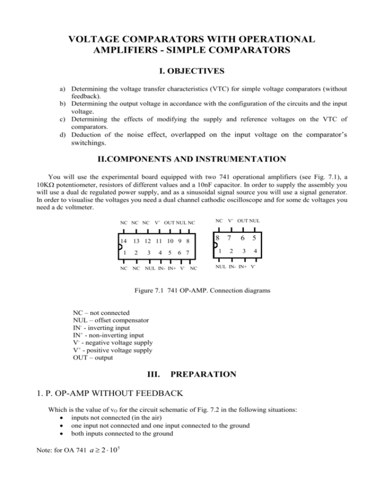
VOLTAGE COMPARATORS WITH OPERATIONAL AMPLIFIERS - SIMPLE COMPARATORS I. OBJECTIVES a) Determining the voltage transfer characteristics (VTC) for simple voltage comparators (without feedback). b) Determining the output voltage in accordance with the configuration of the circuits and the input voltage. c) Determining the effects of modifying the supply and reference voltages on the VTC of comparators. d) Deduction of the noise effect, overlapped on the input voltage on the comparator’s switchings. II.COMPONENTS AND INSTRUMENTATION You will use the experimental board equipped with two 741 operational amplifiers (see Fig. 7.1), a 10K potentiometer, resistors of different values and a 10nF capacitor. In order to supply the assembly you will use a dual dc regulated power supply, and as a sinusoidal signal source you will use a signal generator. In order to visualise the voltages you need a dual channel cathodic oscilloscope and for some dc voltages you need a dc voltmeter. NC NC NC 14 V+ OUT NUL NC 13 12 11 10 9 8 1 2 NC NC 3 4 5 V+ OUT NUL 8 7 1 6 7 NUL IN- IN+ V- NC NC 2 6 5 3 4 NUL IN- IN+ V- Figure 7.1 741 OP-AMP. Connection diagrams NC – not connected NUL – offset compensator IN- - inverting input IN+ - non-inverting input V- - negative voltage supply V+ - positive voltage supply OUT – output III. PREPARATION 1. P. OP-AMP WITHOUT FEEDBACK Which is the value of vO for the circuit schematic of Fig. 7.2 in the following situations: inputs not connected (in the air) one input not connected and one input connected to the ground both inputs connected to the ground Note: for OA 741 a 2 10 5 2. P. COMPARATOR WITHOUT FEEDBACK 2.1. P. INVERTING COMPARATOR You will use the circuit from Fig. 7.3 supplied with V+ = 12V, V- = -12V. A. Waveforms What does vO(t) look like, if vI(t) is a sinusoidal voltage with 5V amplitude and 200Hz frequency, for VREF =0V. But for VREF =4V? Which is the value of the threshold voltage VTh (the value of vI for which the comparator switches)? What does vO(t) look like for a 1V amplitude of vI? B. VTC What does VTC vO(vI) look like for VREF = 0V ? What does VTC vO(vI) look like for VREF = 4V? But for VREF = -4V? C. The effects of modifying the supply voltage What does the vO(t) look like for a sinusoidal vI with a 8V amplitude and 200Hz frequency, VREF =0V, if V+ = 9V, V- = -9V? And if V+= 15V, V- =-9V? 2.2. P. INVERTING COMPARATOR FOR NOISY SIGNAL We want to study the effect of the noise overlapped on the input voltage, on the switches of the comparator without feedback. In Fig. 7.4 the input signal of the comparator (vI) is obtained by summing the sinusoidal input voltage (vs), with 10V amplitude and 200Hz frequency with a triangular signal vn (considered to be the noise) with 2.2V amplitude and 2.7KHz frequency. The summing is made using the R 1 and R2 resistors. The noise voltage is generated by a multivibrator circuit (framed by the marked area). Draw the waveforms for vs, vn, vI. Assume that the threshold voltage VTh = 4V, what does vO(t) look like? 2.3. P. NON- INVERTING COMPARATOR Draw the schematic of a non- inverting voltage comparator with the possibility of adjusting V Th between V+ and VWhat does VTC for the non- inverting comparator look like with VTh=0V IV. EXPLORATIONS AND RESULTS 1. OP-AMP WITHOUT FEEDBACK 1.1 WAVEFORMS Exploration Consider the experimental circuit of Fig. 7.2. V+ vO VFig. 7.2 Op-Amp without feedback 2 The assembly is supplied with a symmetrical differential voltage, V += +12V, V- = -12V from the dual dc regulated power supply. Using a dc voltmeter you will measure vO in the following situations: inputs not connected (in the air) one input not connected and one input connected to the ground both inputs connected to the ground Results vO in the three above mentioned situations. How do you explain that vO ≠ 0 in all these situations? 2. COMPARATOR WITHOUT FEEDBACK 2.1. INVERTING COMPARATOR Consider the experimental circuit of Fig. 7.3 V+ P 10K VREF vO vI VFig. Fig. 10.3 7.3 Basic inverting comparator Basic inverting comparator Exploration The assembly is supplied with a symmetrical differential voltage, V+ = +12V, V- = -12V. vI =8sin2π·200t[V][Hz] from the signal generator. Using P you will adjust the value of VREF; you will measure this value with a dc voltmeter. A. Waveforms Using the calibrated oscilloscope you will visualize vI(t) and vO(t) for VREF=0V and for VREF = 4V. Modify the amplitude of vI to 2V. You will visualize vO(t) and vI(t) for VREF = - 4V. For a vI amplitude of 8V and for VREF = - 4V you will see vO(t) and vI(t) on the oscilloscope. B. VTC Adjust vI =8sin2 π ·200t [V][Hz] and VREF = 0V. With the help of the calibrated oscilloscope, Y-X mode, you will see VTC vO(vI), applying to the two inputs X and Y of the oscilloscope the two voltages vI(t) and respectively vO(t). You will visualize VTC for VREF = 4V You will visualize VTC for VREF = - 4V C. The effects of modifying the supply voltage Supply the assembly with a differential voltage of V+ = +9V, V- = -9V. vI =8sin2 π ·200t[V][Hz] from the signal generator. VREF = 0V by adjusting P. With the help of the oscilloscope, Y- t mode, you will see vI(t) and vO(t). Modify the supply voltages: V+ = +15V, V- = -9V. You will see vI(t) and vO(t) on the oscilloscope. 3 Results A. Waveforms vI(t) and vO(t) for a vI amplitude of 5V, for VREF = 0V and for VREF = 4V. What are the values of the threshold voltage VTh of the comparator in the two situations above? You will find VTh from the waveforms of vI and vO in the following way: you will find the instantaneous values of vI when the comparator is switching. What is the relation between VTh and VREF? vO(t) for a vI amplitude of 1V and VREF = 4V. Why isn’t vO(t) a rectangular voltage anymore ? VTh =? B.VTC VTC for VREF=0V, 4V, -4V. How is VTC modified on the coordinate system vI-vO for a modified VREF? Why? C. The effects of modifying the supply voltage vI(t) and vO(t) for V+= +9V, V- = -9V and for V+= +15V, V- = -9V. What is the effect of modifying the supply voltage on the VTh? Which are the maximum and minimum values of the output voltage of the comparator, V OH and VOL, if modifying the values of the supply voltage? Compare the values of V OH and VOL with the ones you have obtained at A and B. 2.2 INVERTING COMPARATOR FOR NOISY SIGNAL Exploration You will use the experimental schematic of Fig. 7.4 Supply the circuit with V+ = +12V, V- = -12V. Adjust VREF = VTh = 4V (measured with a dc voltmeter) using P. You will calibrate the oscilloscope in the Y-t mode. You will see vn and vI at the same time using the oscilloscope; in order to obtain a more stable image you will use the synchronising buttons. You will also visualise vI and vO. Results vn(t) and vI(t). vI(t) and vO(t). Compare the shape of vO(t) obtained at R2.1.A, for VREF =4V ? What are the differences? Why do they appear? V+ 10K V+ R4 2K2 10K R5 1K8 R3 220nF C Vn P 10K R2 - V VREF vO vI R1 5K1 vs V- 4 Fig. 7.4 Inverting comparator with noisy signal 2.3 NON- INVERTING COMPARATOR Exploration Build the experimental circuit drawn at 2.3. P. vI =8sin2π·200t[V][Hz] from the signal generator. Using P, adjust VREF, which is measured with a dc voltmeter. We will visualize vI(t) and vO(t) for VREF=0V. We will visualize VTC vO(vI) for VREF=0V. Continue the experiment in a similar manner with paragraph 2.1 for waveforms and VTC. Results vI(t) and vO(t) VTC What is the difference of the VTC compared with the one obtained at 2.1 The results will be presented in a similar manner with the ones in paragraph 2.1. 5
