Equilibrium of Concurrent Forces Lab Experiment
advertisement
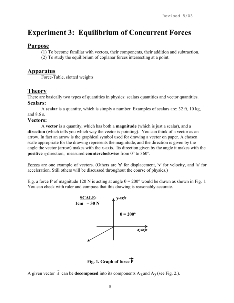
Revised 5/03 Experiment 3: Equilibrium of Concurrent Forces Purpose (1) To become familiar with vectors, their components, their addition and subtraction. (2) To study the equilibrium of coplanar forces intersecting at a point. Apparatus Force-Table, slotted weights Theory There are basically two types of quantities in physics: scalars quantities and vector quantities. Scalars: A scalar is a quantity, which is simply a number. Examples of scalars are: 32 ft, 10 kg, and 8.6 s. Vectors: A vector is a quantity, which has both a magnitude (which is just a scalar), and a direction (which tells you which way the vector is pointing). You can think of a vector as an arrow. In fact an arrow is the graphical symbol used for drawing a vector on paper. A chosen scale appropriate for the drawing represents the magnitude, and the direction is given by the angle the vector (arrow) makes with the x-axis. Its direction given by the angle it makes with the positive x-direction, measured counterclockwise from 0 to 360. Forces are one example of vectors. (Others are 'x' for displacement, 'v' for velocity, and 'a' for acceleration. Still others will be discussed throughout the course of physics.) E.g. a force P of magnitude 120 N is acting at angle = 200 would be drawn as shown in Fig. 1. You can check with ruler and compass that this drawing is reasonably accurate. y-axis SCALE: 1cm = 30 N θ = 200º x-axis Fig. 1. Graph of force P A given vector A can be decomposed into its components Ax and Ay (see Fig. 2.). 8 Experiment 3 y A Ay θ Ax Fig. 2 Vector A decomposed. x Note that the vector, A, is in boldface type but the components, Ax and Ay, are in plain face type. There are two ways to express the vector A: 1) magnitude A, and angle , and 2) the two components: Ax and Ay. From magnitude and angle to components: Ax = A cos and Ay = A sin (1) From the components to the magnitude and angle: A = Ax2 + Ay2 and = tan-1 (Ay /Ax). (2) Important: There are TWO solutions of the equation tan = Ry/Rx. To find the correct value of note that: (1) Both x and y are positive in quadrant 1 (2) x is negative and y is positive in quadrant 1 (3) Both x and y are negative in quadrant 3 (4) x is positive and y is negative in quadrant 1 Now you can apply these relations to any vector quantity in physics. Vector Addition: In order to add two vectors add only the components, which point in the same directions. So for example if you want to add vector A and vector B to obtain the resultant vector, C, then you would add the value of Ax to Bx to obtain the value of Cx and the value of Ay to By to obtain the value of Cy. Now vector C has its own two components denoted by Cx and Cy. Naturally these two are the sums of the previous two components, namely: Cx = Ax + Bx and Cy = Ay + By. 9 Experiment 3 You can add more than one vector the same way: The sum S of adding forces F 1, F 2, F 3,… can be found by summing the components: Sx = Fx = algebraic sum of all Fx-es. Sy = Fy = algebraic sum of all Fy-s. S = magnitude of the resultant S = Sx2 + Sy2 = angle of S (0 360) = tan-1 (Sy /Sx) (3) Procedure Preliminary Part (a) Your instructor will briefly explain how to operate the force-table. (b) The holders each have mass. This must be taken into account when calculating the total applied force of the masses at the ends of the strings. (c) When all of the applied forces are in equilibrium, then the ring will remain centered around the central pin. If there is any unbalanced force, then the ring will be pulled in that direction and the student must then determine how much mass to add (or subtract) in order to achieve a balance of all the forces. 10 Experiment 3 string central pin ring string string Fig. 4. Well-centered forces. Using only two holders (the other two strings are to hang free) set one pulley at 127, and the other at 307. Load each holder with 550 grams. After all adjustments, verify that the ring is perfectly centered on the central pin. This is Newton's third law, namely: F = 0. (d) Remove 50 grams from one mass holder. Note that the ring is immediately pulled by the heavier force (550 gms > 500 gms). This is due to the imbalance of the two forces. Therefore you can see that when a net (unbalanced) force is present, an acceleration (i.e. motion) begins to occur. This is Newton's second law, namely: F = m.a. NOTE: Grams are units of mass, not force. As such you must multiply all mass quantities by the factor of gravity (g = 9.8 m/s2) to yield the appropriate quantity of a force. In other words, here W = mg. Procedure Part I: Finding the Resultant (1) Set a pulley at 0 and load the string with V1 grams. Set the second pulley at 90 and load with V2 grams. Calculate the magnitude of the sum S of these two forces, as well as its angle , using the formulas (2). (2). Report these calculations (for S and ) on your data-sheet with an accuracy of three significant digits. 11 Experiment 3 (3) Checking the sum calculation: Set up the third pulley at the angle = + 180 and load it with as many grams as is the value of S. This is the opposing force OV (the equilibriant of V1 and V2). Leave the fourth string slack. Make any adjustments and verify that the ring is perfectly centered on the pin (see Fig. 4.). Record this observation on your data-sheet. DO NOT PROCEED UNTIL THIS IS ACHIEVED. If you are not able to find your mistake, CALL YOUR INSTRUCTOR. Procedure Part II: Finding the Equilibrant (the opposing force) (4) Set two pulleys at angles 1 and 2, loading them with P1 and P2, respectively (you may choose any values you wish for P1 and P2). By trial and error set up the third string at the correct angle and loaded with the correct mass, to balance the two forces P1 and P2. This is the opposing force OP of P1 and P2. Record its magnitude and angle. No calculations are required. (5) With all forces in equilibrium, increase the load on the equilibrant string in steps of 1 gm. Record the smallest change that will cause the ring to move. Call this value OP. This is the error in OP caused by friction in the pulleys. (6) Return to the original magnitude of OP. By shifting the equilibrant-string pulley sideways, measure and record as the smallest change in angle causing an observable disturbance. Procedure Part III: Equilibrium of Four Forces 7) Load three strings with masses as in Fig. 5. Using trial and error, set up a fourth string to balance the three forces. Record the magnitude and the angle of the opposing force O. y (90º) F2 F1 x (0º) (8) Repeat (5) and (6) as in Part II. F3 Fig. 5 BEFORE YOU LEAVE THE LAB: (1) Make sure that you have your data-sheet initialed by your instructor. (2) Make sure you clearly understand the requirements of your lab instructor. (3) You will have to add forces in Part III graphically in your report. Make sure you know how to make proper and accurate drawings. 12 Experiment 3 Lab Report Part I Analysis (1) Answer the following: If V1 was acting at 45 (instead of 0) and V2 at 135 (instead of 90), would either the angle or the magnitude, or both, of their sum S change? Can you answer this question without any calculations? Part II Analysis (2) From your assigned values of P1, P2, 1, and 2, calculate the components of P1 and P2, and their sum S, displaying them in Table 1. TABLE 1 x comp y comp P1 P2 S Also, calculate the magnitude and the angle of S and display them in Table 2, along with the measured values for opposing force OV. TABLE 2 magnitude (gm) (º) S (calculated) OP (measured) (3) Calculate these two quantities: d = (S-OP) x 100% (%-discrepancy between S and OP). S u = OP x 100% (%-uncertainty in OP). OP On the basis of the quantity 'u' (this is your experimental uncertainty in the magnitude OP, explain what should be the major reasons of your discrepancy d between OP and S. 13 Experiment 3 Part III Analysis (4) Calculate all quantities required in Table 3 (Only for Part III of the experiment), and round them to 3 significant figures. (5) Calculate quantities “d”, and “u” as in item (3) above and make your comments. (6) Forces F1, F2 and F3 can be added graphically, as sketched in Fig. 6. Draw such a diagram on a sheet of graph paper using a sharp pencil, a ruler, a triangle, and a protractor. Select a sufficiently large scale to utilize the entire sheet for greater accuracy. (Don’t forget to write down the scale you used for your graph.) TABLE 3 x comp. y comp. F1 F2 F3 Fx = Scalc Fy = θS = Smag = (7) Measure the magnitude of the sum S from your graph and enter it in Table 4, along with the other two values listed. TABLE 4 Scale: x--direction x--direction QUANTITY Smag from Calculations (4) x--direction O from Experiment F2 F3 S F1 S from Graphical Work Fig. 6 State clearly which one of the three values is most reliable, and why. 14 VALUE (gm)
