Supplementary_information
advertisement
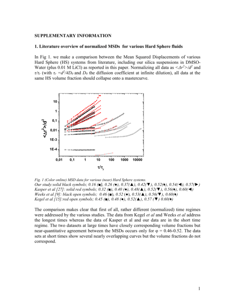
SUPPLEMENTARY INFORMATION 1. Literature overview of normalized MSDs for various Hard Sphere fluids In Fig 1. we make a comparison between the Mean Squared Displacements of various Hard Sphere (HS) systems from literature, including our silica suspensions in DMSOWater (plus 0.01 M LiCl) as reported in this paper. Normalizing all data as <Δr2>/d2 and τ/τr (with τr =d2/4D0 and D0 the diffusion coefficient at infinite dilution), all data at the same HS volume fraction should collapse onto a mastercurve. 10 2 0,01 <r >/d 0,1 2 1 1E-3 1E-4 0,01 0,1 1 10 100 1000 10000 r Fig. 1 (Color online) MSD data for various (near) Hard Sphere systems. Our study:solid black symbols; 0.16 (■), 0.26 (●), 0.37(▲), 0.42(▼), 0.52(♦), 0.54(◄), 0.57(►) Kasper et al [27]: solid red symbols; 0.32 (■), 0.40 (●), 0.48(▲), 0.52(▼), 0.56(♦), 0.60(◄) Weeks et al [9]: black open symbols; 0.46 (■), 0.52 (●), 0.53(▲), 0.56(▼), 0.60(♦) Kegel et al [15]:red open symbols; 0.45 (■), 0.48 (●), 0.52(▲), 0.57 (▼) 0.60(♦) The comparison makes clear that first of all, rather different (normalized) time regimes were addressed by the various studies. The data from Kegel et al and Weeks et al address the longest times whereas the data of Kasper et al and our data are in the short time regime. The two datasets at large times have closely corresponding volume fractions but near-quantitative agreement between the MSDs occurs only for φ = 0.46-0.52. The data sets at short times show several nearly overlapping curves but the volume fractions do not correspond. 1 2. Particle size dsitribution Fig. 2 shows a Scanning Electron Microscopy image of our silica particles, and the size distribution obtained from this image. Fig. 2 (Color online): SEM image of our silica particles, and the size histogram Fitting with a Gauss distribution yielded an average diameter of 1.15 μm and a standard deviation of 8% (92 nm). This fitting curve, indicated with red dots, ignores two particles. For calculating volume fractions, the average particle volume π<d3>/6 is generally more appropriate than taking π<d>3/6. However for the present distribution the difference between <d3>1/3 and <d> was ≈ 12 nm. In figure 3, we show the variation of overall volume fraction (OVF) as a function of H. Variation of OVF can also be extracted from Figure 6 as averaging over local volume fractions give OVF.The variation in OVF is less than %5 and does not follow a trend. 2 Volume fraction () 0,42 0,40 0,38 0,36 0,34 0,32 5 10 15 20 H (m) Figure 3 Overall volume fraction calculated for varying H for three samples used in experiments. The volume of calculation has been 65*65*H µm3. The volume fraction has been calculated by counting number of particles in the box, correcting for the particles at the edges and multiplying with the mean particle volume. 3. Alternative versions for Figure 5 and Figure 6 3 2 2 <r >=10 s (m ) 0.1 0.01 H 1E-3 1E-4 1 10 ZFP (m) Figure 4 of Appendix. Alternative version of Figure 5: Dark solid line with open squares correspond to interpolated MSD(t=10s) with Peak values taken from Figure 6. FIG. 5: Spatially resolved behavior of MSD(τ =10s) for the fluid at φ=0.33, confined at different gap heights H. Correspondence between H (µm) and symbols: 20 (■), 16(●), 12(▲), 8(▼) and 4(♦). The symbol belongs to the experiment where the second confining surface is far away ( H ). Corresponding open symbols indicate ‘bulk’ MSD values calculated from the local volume fraction showing what MSD(τ=10s) would be if the system was bulk and dynamics solely governed by volume fraction. The open symbols has been calculated from the linear fit to a characteristic curve in the inset of Figure 6. The error bars has been calculated from different fits to inset of Figure 6. The dotted part of open symbols indicate extrapolation.See text for further details. 4 1.0 C O N V O L U T ED 0 .6 0.8 0.6 0 .5 0 .4 0 .3 0 .2 0 .1 s 0 .0 2 4 6 8 10 12 14 16 18 20 22 24 Z ( m ) 0.4 0.2 0.0 0 10 20 30 Z(m) Figure 5 of Appendix.Alternavive version of Figure 6 indicating the peak values used for calculation in Figure 5 with open symbols. FIG. 6 (color online): Geometirc Volume fraction(φ s) vs Z-direction for different confinement gaps: Correspondence between H (µm) and symbols: 20 (■), 16(●), 12(▲), 8(▼) and 4(♦). The symbol belongs to the experiment where the second confining surface is far away ( H ). φ indicates local volume fraction calculated in a bin. Inset: Convoluted volume fraction(φ) vs Z-histogram, as needed for generating reference MSD data at τ=10 s in Fig. 5. Plot symbols indicate which φ values were used for this purpose. See text for further details. 5


