1. CLIC concept
advertisement

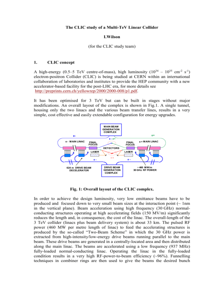
The CLIC study of a Multi-TeV Linear Collider I.Wilson (for the CLIC study team) 1. CLIC concept A high-energy (0.5–5 TeV centre-of-mass), high luminosity (1034 – 1035 cm-2 s-1) electron-positron Collider (CLIC) is being studied at CERN within an international collaboration of laboratories and institutes to provide the HEP community with a new accelerator-based facility for the post-LHC era, for more details see http://preprints.cern.ch/yellowrep/2000/2000-008/p1.pdf. It has been optimised for 3 TeV but can be built in stages without major modifications. An overall layout of the complex is shown in Fig.1. A single tunnel, housing only the two linacs and the various beam transfer lines, results in a very simple, cost effective and easily extendable configuration for energy upgrades. M AIN BEAM GENERATION COM PLEX e+ ee - e+ e - M AIN LINAC FINAL FOCUS FINAL FOCUS e + M AIN LINAC DETECTORS LASER e- 624 m DRIVE BEAM DECELERATOR LASER DRIVE BEAM GENERATION COM PLEX e~ 460 M W/m 30 GHz RF POWER Fig. 1: Overall layout of the CLIC complex. In order to achieve the design luminosity, very low emittance beams have to be produced and focused down to very small beam sizes at the interaction point (~ 1nm in the vertical plane). Beam acceleration using high frequency (30 GHz) normalconducting structures operating at high accelerating fields (150 MV/m) significantly reduces the length and, in consequence, the cost of the linac. The overall-length of the 3 TeV collider (linacs plus beam delivery system) is about 33 km. The pulsed RF power (460 MW per metre length of linac) to feed the accelerating structures is produced by the so-called “Two-Beam Scheme” in which the 30 GHz power is extracted from high-intensity/low-energy drive beams running parallel to the main beam. These drive beams are generated in a centrally-located area and then distributed along the main linac. The beams are accelerated using a low frequency (937 MHz) fully-loaded normal-conducting linac. Operating the linac in the fully-loaded condition results in a very high RF-power-to-beam efficiency (~96%). Funnelling techniques in combiner rings are then used to give the beams the desired bunch structure with the concomitant increase in intensity, in this process the bunch spacing is reduced in stages from 64 cm to 2 cm, and the beam current is increased from ~5.7 to ~181 A. It is generally accepted that CLIC technology is the only viable technology for multi-TeV colliders. 2. Main features The CLIC accelerating gradient of 150 MV/m is very ambitious, and results in a total linac length of 27.5 km for a 3 TeV collider, or 4.8 km for 0.5 TeV. CLIC technology enables the energy reach of a future linear collider to be extended possibly even up to 5 TeV. The CLIC design is based on the “two-beam scheme” in which the 30 GHz rf power for main linac acceleration is extracted from a series of low-energy high-current drive beams running parallel to the main linac. 3. Strong points CLIC is a collider at the high-energy frontier beyond LHC The linac is very compact – the two linac length for a 3 TeV collider is 27.5 km. The fact that there are no active rf components in the main linac means that CLIC has a single small-diameter (3.8m) tunnel. A particularly attractive feature of the CLIC scheme is that to upgrade the energy of the collider, the only change in the rf power system required is a change in the pulse length of the modulators which drive the low frequency (937 MHz) klystrons and not an increase in the number of klystrons (the nominal pulse length for the 3 TeV collider is 100 microsec). Only a relatively small number of klystrons are required for the CLIC scheme – this is independent of the final energy. The power for each drive-beam accelerator is supplied by 352 40 MW multi-beam klystrons which are grouped together in the central area of the facility. This central location facilitates power distribution, cooling and maintenance work. The energy required for acceleration is transported, compressed and distributed using high power electron beams – conventional systems generate the rf power locally and then transport it over long lossy waveguides – the CLIC energy is only converted into rf power where it is required (typically 60 cm from each CLIC main linac accelerating structure). The use of a high rf frequency (30 GHz) reduces the peak power that is required to achieve the 150 MV/m accelerating gradient. 4. Weaker points There is a fixed investment cost for the drive beam generation system of the CLIC two-beam scheme which is independent of energy. This makes the scheme less cost effective at low energies but this disadvantage disappears at high energies. Conditioning of the drive and main linacs with rf power to acceptable break-down rates is more complicated for a two-beam scheme than for a conventional scheme with conventional rf power sources. This will almost certainly require the provision of some over-capacity in the basic design and the ability to turn PETS structures ON and OFF. The higher CLIC rf frequency makes the scheme more sensitive to alignment errors and ground stability. 5. Summary of what has been achieved Basic designs of all CLIC sub-systems and essential equipment have been made but more design work is required. Details of the work already accomplished is summarised in 645 CLIC Notes and other publications, for more details see http://ps-div.web.cern.ch/ps-div/CLIC/Publications/CLICNotes.html The technical feasibility of two-beam acceleration has been demonstrated in CLIC Test Facility 2 (CTF2). In this test, the energy of a single electron bunch was increased by 60 MeV using a string of 30 GHz accelerating cavities powered by a high intensity drive linac. The nominal CLIC accelerating gradient of 150 MV/m at the nominal pulse length of 70 ns has been obtained during the last CTF3 run of 2005 using molybdenum-irises in 30 GHz copper structures. This is a very important result for the CLIC study, more effort however has to be invested to get the breakdown rate down. An experimental demonstration of the principle of the bunch combination scheme has been made at low charge using a modified layout of the former LEP Pre-Injector (LPI) complex. A successful demonstration of full-beam-loading operation has been made using the injector of the new CLIC Test Facility 3 (CTF3). A prototype CLIC quadrupole has been stabilized to the 0.5 nm level in a relatively noisy part of the CERN site using commercially available state-of-the-art stabilization equipment. Sub-nm stability is required to collide nm-size beams. The active pre-alignment system has been tested in CTF2 and held components in place during normal operation of the two-beam test accelerator within a window of 2-3 microns. This meets the present CLIC requirement. 6. What remains to be demonstrated There are two categories of feasibility issues that remain to be demonstrated. 1. CLIC-technology-related feasibility issues 2. Issues common to other linear collider studies The new CLIC Test Facility CTF3 is being built to demonstrate all the key CLICtechnology-related issues of the CLIC scheme. Issues common to other linear collider studies are being studied within the framework of the existing world-wide linear collider collaborations, and in particular in Europe, within the EU FP6 Programme. 7. CLIC-technology-related feasibility issues The International Technical Review Committee has indicated a number of crucial items for which the CLIC Collaboration has still to provide a feasibility proof (the so-called R1 items) and also a number of issues, which must be investigated in order to arrive at a Conceptual Design (R2 items). It is proposed to focus attention initially on the "CLIC-Technology-Related" issues as opposed to issues which are common to all linear collider studies. Adopting this approach, there are three R1 key feasibility issues and two R2 issues, which have to be demonstrated first before any further work can be envisaged. The three R1 issues are: R1.1 Test of damped accelerating structure at design gradient and pulse length R1.2 Validation of the drive beam generation scheme with a fully loaded linac R1.3 Design and test of an adequately damped power-extraction structure, which can be switched ON and OFF The two R2 issues are: R2.1 Validation of beam stability and losses in the drive beam decelerator, and design of a machine protection system R2.2 Test of a relevant linac sub-unit with beam All five of these key feasibility issues can be demonstrated in CTF3. One important CLIC-technology-related feasibility issue of the CLIC twobeam scheme which was not listed by the TRC is the very precise synchronization required between main and drive beams to avoid excessive luminosity loss due to energy variations. The scheme foreseen to do this measures and corrects the drive beam phase within a feedback system using the main beam as a reference but requires the timing of both main and drive beams to be measured to a precision of about 10 fs. This requires a new development but seems to be just feasible. This problem is being studied within the EUROTeV Design Studies as part of Work Package 5 (DIAG / TPMON). The fact that CLIC is not powered by small modular sub-units complicates the demonstration of its technical feasibility. 8. Issues specific to multi-TeV linear colliders The achievement of the luminosity target is a severe challenge in CLIC. This is because nanometer-size beams have to be collided in the presence of time-varying perturbations, the main beam pulse is essentially too short to use intra-beam feedback, and because the luminosity cannot be measured directly at the required speed. To meet this challenge, complex tuning of the beam size and the luminosity at the interaction point is required and it is essential that these tuning procedures converge significantly faster than the perturbing conditions degrade. To demonstrate this feasibility issue, detailed, realistic studies of the tuning of the machine in presence of static and dynamic imperfections are mandatory to determine the time needed for convergence and to ensure that the machine remains stable over these times. The design of the CLIC extraction line for the spent beam with a 100% energy spread (or 200% since both electrons and positrons are created) is also considered to be a severe challenge - this will be the case for all high-energy colliders with very strong beam-beam interactions. 9. Accelerated R&D programme The present situation concerning the definition of a linear electron-positron collider and the perspective of its implementation inside a worldwide international cooperation are such that it was decided to accelerate the tests of feasibility of the CLIC concept in order to arrive before 2010 at a firm conclusion on its possible use. The 2010 end date for this activity was chosen because LHC results will hopefully be available by that time, and any previous technical choices of design parameters for a new electron-positron collider will logically be reviewed and reassessed before launching a new project. It therefore seems appropriate that the assessment of the CLIC design concept be available at that time, should the need for a higher energy then be recognised. CERN Council endorsement The CERN Council, in its special 129th Session held in Rome on 19 July 2004, confirmed its endorsement of these accelerated R&D activities to demonstrate the feasibility of the key issues of the CLIC scheme, before 2010. CLIC multi-lateral collaboration An international multi-lateral collaboration of institutes and funding agencies has been created to finance and carry out the accelerated CLIC R&D programme. This collaboration formally came into being on the 30th November 2005 with the joint signing of the MoU. CTF3 A schematic layout of the facility is shown in Fig.2. 3.5 2100 b of 2.33 3.5AA–-2100 bunches of 2.33nC nC – 150 MeV – 1.4s x2 Delay loop 42 m Drive Beam Accelerator X 5 HG test Stand TBL CLEX Combiner Ring 84 m Two-beam test stand Relevant linac subunit Probe Beam 35 A - 150 MeV – 140 ns Fig. 2 Schematic layout of the CLIC Test Facility CTF3 10. Planning The important construction and installation phases together with the test periods of the key feasibility issues are given in Fig.3. 2004 2005 2006 2007 2008 Drive Beam Accelerator 30 GHz high-gradient test stand 30 GHz high-gradient testing (4 months per year) R1.1 feasibility test of CLIC accelerating structure Delay Loop Combiner Ring R1.2 feasibility test of drive beam generation CLEX R1.3 feasibility test of PETS structure Probe Beam R2.2 feasibility test of relevant CLIC linac sub unit Test beam line R2.1 Beam stability bench mark tests Fig. 3 11. Important CTF3 milestones. CTF3 Status December 2005 The status of the CTF3 test facility and test results obtained at the end of 2005 are as follows : The linac has been installed and commissioned and full-beam-loading operation demonstrated. The delay loop has been installed and first commissioning tests carried out including a first demonstration of recombination. The high-gradient test stand is operational and the CLIC nominal gradient and pulse length have been demonstrated. Full details of the progress was presented at the 10th CTF3 Collaboration Meeting at CERN in November 2005 – see http://ctf3.home.cern.ch/ctf3/New_collab_meet.htm Ian Wilson 13 January 2006 2009


