Chapter 3 : Scattering, Attenuation and Speckle
advertisement
Chapter 3 : Scattering, Attenuation and Speckle
I.
Scattering
Pulse echo imaging relies on reflected waves (echoes) to form an image and the
reflection occurs due to acoustic impedance differences. In the case that the
objects which cause reflection are much larger than the wavelength of the incident
waves, it is also called specular reflection. Using typical impedance values in the
body, we find that the energy reflected is about -20 to -50 dB lower than the
energy of the incident waves. In other words, not much acoustic energy is lost at
the boundary of two different types of soft tissue.
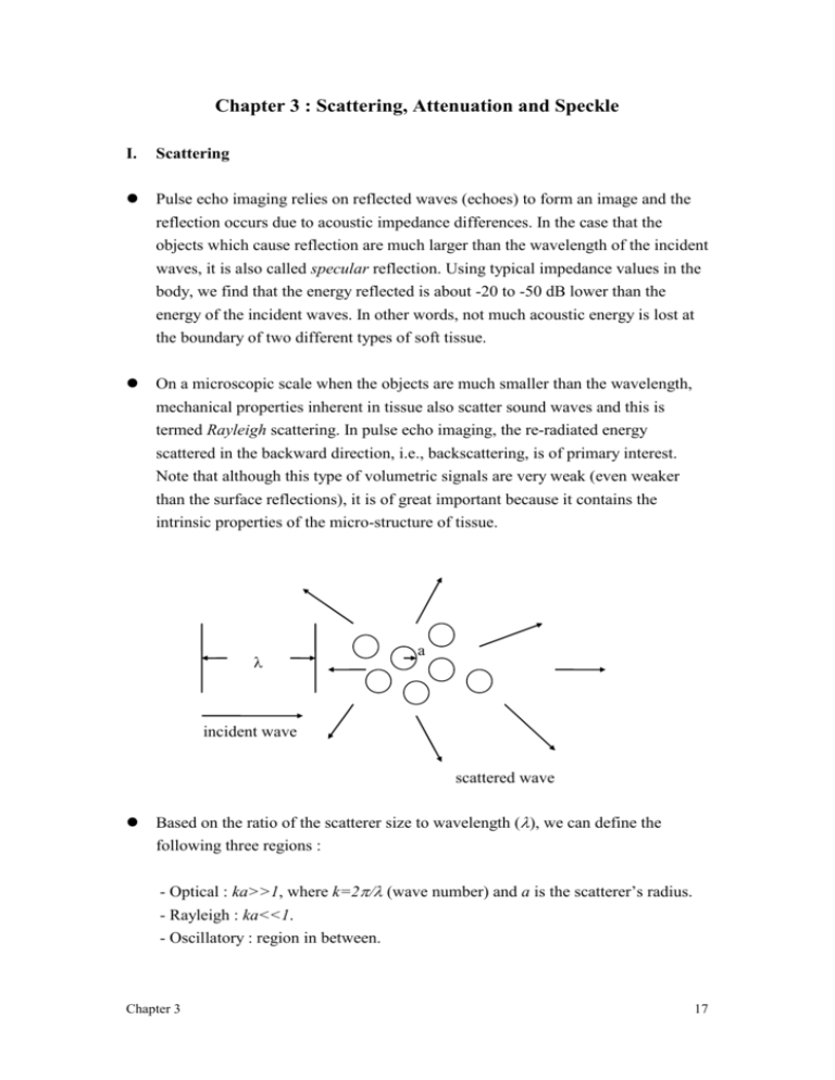
On a microscopic scale when the objects are much smaller than the wavelength,
mechanical properties inherent in tissue also scatter sound waves and this is
termed Rayleigh scattering. In pulse echo imaging, the re-radiated energy
scattered in the backward direction, i.e., backscattering, is of primary interest.
Note that although this type of volumetric signals are very weak (even weaker
than the surface reflections), it is of great important because it contains the
intrinsic properties of the micro-structure of tissue.
a
incident wave
scattered wave
Based on the ratio of the scatterer size to wavelength (, we can define the
following three regions :
- Optical : ka>>1, where k=2 (wave number) and a is the scatterer’s radius.
- Rayleigh : ka<<1.
- Oscillatory : region in between.
Chapter 3
17
A few parameters can be defined to help us quantify scattering. (1). Scatter cross
section (s) is defined as the ratio of the total power scattered by the object to the
incident energy. Similarly, backscatter cross section (b) can be defined as the
ratio of the total power backscattered by the object to the incident energy. (2).
For a collection of scatterers, backscatter coefficient (), which is defined as the
backscattering cross section per unit volume of scatterers, is usually used to
represent the backscattering efficiency. In some cases, the backscatter coefficient
is further normalized to solid angle with an additional unit of sr-1 (a sphere is
equal to 4 steradians).
In the Rayleigh scattering region, a relatively simple approach can be taken to
obtain an analytical expression for the scatter cross section (s) by using principle
of superposition and the Born approximation (ignoring secondary scattering
inside the objects). Under these conditions, we have
s k 4a 6 ,
where k is the wave number and a is the radius of the object.
The ultimate goal of studying ultrasonic scattering in the body is to characterize
tissue quantitatively. Due to the complexity of biological tissues, however, it is
extremely difficult to use simple analytical expressions to describe scattering in
the body. In addition, dependencies on animal species, tissue types and
experimental techniques still sometimes produce inconsistent in vitro results. In
fact, the fundamental scattering structures in most of the tissues are still unknown
to this date.
Ultrasonic scattering in biological tissues is primarily determined by size and
acoustic properties of tissue structures. It is believed that composition of cells,
blood vessels and ductal networks plays an important role in the ultrasonic
scattering structure. Additionally, the size of tissue structure may also be a
dominant factor. For example, it has been shown that the volume of red blood
cells affects ultrasonic scattering in blood to a great extent. However, for most
biological tissues, which are typically more complex than blood, the scattering
mechanisms have not been fully understood.
(Very) Roughly speaking, assuming the frequency of the incident waves is f, the
backscatter coefficient is proportional to f 4 for blood, f 3 for myocardium,
Chapter 3
18
and f 1. 52 . 5 for other soft tissues. Note that the backscattering from blood is the
closest to Rayleigh scattering. Also note that as the frequency increases, signals
backscattered from blood also increase faster than those backscattered from other
soft tissues.
Some typical numbers for blood and heart tissue
Frequency (MHz)
(mm-1) heart tissue
(mm-1) blood
2.5
4.310-5
0.510-6
3.75
1.510-4
2.610-6
5.0
5.010-4
8.210-6
III. Attenuation
Reflection and scattering result in signal loss as a sound wave propagates in tissue.
However, this type of redistribution of energy only accounts for a small amount
of attenuation. It is believed that the relaxation process, which causes absorption,
is the major source of attenuation.
Relaxation occurs when the pressure change resulting from a reduction of volume
occupied is not quite in phase with the change in density, and energy is thereby
changed to heat. In biological tissues, the product of ultrasonic absorption and
wavelength is roughly constant in the diagnostic frequency range. In other words,
it is reasonable to assume that the absorption is linearly proportional to the
frequency.
Fundamentally, the maximum penetration depth is determined by the frequency
dependent attenuation and clinical safety requirements. Different clinical
applications require different field of view (including penetration depth), thus
requiring different ultrasonic carrier frequencies.
Assuming I(z) is the incident wave and let the energy loss per unit length is
proportional to the intensity, we have
I(z)_
A
z
Chapter 3
I(z+z)
z+z
19
A I ( z z ) A I ( z ) 2A I ( z ) z .
If z 0 , then
I ( z )
2 I ( z )
z
.
2z
I ( z ) I 0e
Assuming attenuation is linearly proportional to frequency in tissue, we have
f .
Therefore, we can define the following characteristic propagation function for a
plane wave propagating in tissue
H ( z , f ) e ( fz j2fz / c )
and we have the following relation for intensity
2
I ( z , f ) I 0 H ( z , f ) I 0e 2fz .
The attenuation in dB is defined as
I ( z , f )
10 log10
20 ( log10 e ) fz 8 . 69fz ,
I0
where is defined in (nepers)/cm/MHz. In dB, dB is in units of dB/cm/MHz and
dB 8 . 69 nepers . In soft tissue, dB is typically assumed to be 0.5 dB/cm/MHz.
In pulse echo imaging, signals reflected from a depth of R actually have a total
propagation distance of 2R. Therefore, assuming the center frequency of the
sound waves is f0, signals received from a depth of R is dB*2R*f0 dB lower than
the transmitted waves.
Since attenuation is both frequency and depth dependent, the frequency contents
of the transmitted sound waves are also affected as they propagate in tissue.
Assume a wide band (as opposed to a continuous wave) Gausian pulse with the
following power spectrum
Chapter 3
20
2
St ( f ) e
(
f f0 2
)
.
Also assuming specular and ignoring backscattering, the round trip received
signal from a depth of R is
2
2
S r ( R , f ) S t ( f ) e 4Rf e
(
f f0 2
) 4Rf
.
The above equation can be re-arranged as the following
2
Sr ( R , f ) e
(
f f1 2
)
e 4R ( f
0
R )
2
,
where f 1 f 0 2 2R . In other words, the received signal is attenuated by the
amount indicated in the second term and more importantly, the center frequency
of the propagating pulse is shifted downward as the wave propagates. The
bandwidth, on the other hand, remains the same. Therefore, the lateral resolution,
which is a strong function of center frequency, is affected while the axial
resolution, which is determined by the bandwidth, is not changed.
2R
R 0
f
III. Speckle
Speckle is a common phenomenon in coherent (i.e., phase sensitive) imaging
systems. It comes from coherent interference of scatterers (i.e., linear summation
by the transducer of echoes from scatterers) and it appears as a granular structure
superimposed on the image. Speckle is an artifact degrading target visibility and
does not represent any inherent tissue properties. It is one of the primary
limitations on detecting low contrast lesions in ultrasonic imaging.
The statistical properties of speckle are based on the approach taken by J.W.
Goodman for laser speckle. In ultrasound, speckle occurs when the size of
Chapter 3
21
scatterers is small compared to a wavelength and there are many scatterers within
one sample volume. This is true for diagnostic ultrasound since most scatterers in
soft tissue have a size less than 100m and the size of a typical sample volume
(i.e., spatial resolution) is at the order of mm. In this case, the speckle pattern
statistics are independent of the scattering structures and are a function only of the
imaging system and its relative distance to the target.
Speckle can be modeled by a random walk in the complex plane where each step
in the walk represents the signal received by the transducer from a single scatterer
within the resolution volume. Since these scatterers are in the same sample
volume, the signals from them are coherently summed when received by the
system. The sum can therefore be represented by a complex number shown in the
following drawing. Note that the amplitude of each individual phasor represents
the strength of the signal from the particular scatterer, whereas the phase of the
phasor is related to the propagation delay (i.e., distance between the scatterer and
the transducer).
sample volume
transducer
Im
Re
Let a k ( 1 k N ) be the signal received from a particular scatterer with a
phase k , we have the following equations for the summed signal A :
Chapter 3
ReA
1
ImA
1
N
N
N
ak
k
cos k
1
N
ak
k
.
sin k
1
22
Assuming the following statistical properties:
- The amplitude a k and the phase k of the kth elementary phasor are
statistically independent of each other and of the amplitudes and phases of all
other individual phasors.
- There are many scatteres in the sample volume and their locations are randomly
distributed. Therefore, the phases k are uniformly distributed between - to
It then follows from the central limit theorem that as N (practically,
N ~ 10 ) , Re{A} and Im{A} are asymptotically Gaussian. Combining this with
other first and second order statistics, we find the joint probability density
function of the real and imaginary parts of A is
p Re{ A}. Im{ A}
1
2
e
2
Re{ A }2 Im{ A }2
2 2
,
where
N
1
2
N
k
2
ak
.
2
1
This function is also known as a circular Gaussian density function.
It is then straightforward to see that the intensity of the summed signal
I Re{ A }2 Im{ A }2 is exponentially distributed, i.e., (for I 0 )
pI
1
2 2
e
I
2 2
and the amplitude E I is Rayleigh distributed, i.e., (for I 0 )
pE
E
2
e
E2
2 2
.
Some interesting properties for the above two density functions are listed as
follows:
Chapter 3
23
SNRI
SNRE
I
I
1
E
E
2
/2
4
2
,
1/ 2
/2
1.91
1/ 2
where I and E are standard deviations of the intensity and the amplitude,
respectively.
Therefore, speckle noise can be viewed as a multiplicative noise, where the noise
increases as the mean increases. In other words, stronger signals also suffer from
higher noise and hence they are not easier to be detected.
Ultrasonic images are often displayed on a logarithmic scale so that signals across
a wide dynamic range can be shown at the same time. Furthermore, the speckle
noise also becomes additive on a logarithmic scale. Define D as
D ( dB ) f ( I ) 10 log10 (
I
),
I0
where I 0 is an arbitrary reference signal. Expanding the function f in a Taylor
series about the statistical mean
I , we have
R ,
D f ( I ) I I f I
where R is a remainder. Ignoring R, we have
10 I
ln 10 I 2 .
2
D f ( I ) I
2
2
2
2
D 4 . 34dB
In other words, speckle noise in a logarithmically processed display becomes a
fixed additive noise. This noise (4.34dB) fundamentally limits the detectability of
low contrast lesions using diagnostic ultrasound.
There are numerous techniques developed to reduce the speckle noise. Almost
all of them, however, result in degradation in spatial resolution. More details
will be covered in Chapter 7.
Chapter 3
24

