The CFRP Primary support structure for the MIRI Instrument
advertisement
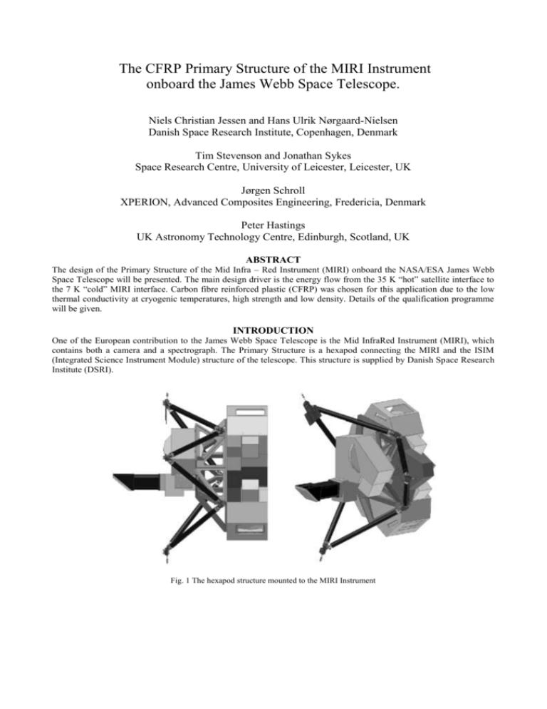
The CFRP Primary Structure of the MIRI Instrument onboard the James Webb Space Telescope. Niels Christian Jessen and Hans Ulrik Nørgaard-Nielsen Danish Space Research Institute, Copenhagen, Denmark Tim Stevenson and Jonathan Sykes Space Research Centre, University of Leicester, Leicester, UK Jørgen Schroll XPERION, Advanced Composites Engineering, Fredericia, Denmark Peter Hastings UK Astronomy Technology Centre, Edinburgh, Scotland, UK ABSTRACT The design of the Primary Structure of the Mid Infra – Red Instrument (MIRI) onboard the NASA/ESA James Webb Space Telescope will be presented. The main design driver is the energy flow from the 35 K “hot” satellite interface to the 7 K “cold” MIRI interface. Carbon fibre reinforced plastic (CFRP) was chosen for this application due to the low thermal conductivity at cryogenic temperatures, high strength and low density. Details of the qualification programme will be given. INTRODUCTION One of the European contribution to the James Webb Space Telescope is the Mid InfraRed Instrument (MIRI), which contains both a camera and a spectrograph. The Primary Structure is a hexapod connecting the MIRI and the ISIM (Integrated Science Instrument Module) structure of the telescope. This structure is supplied by Danish Space Research Institute (DSRI). Fig. 1 The hexapod structure mounted to the MIRI Instrument ENVIRONMENTS The Primary Structure supporting MIRI must sustain the launch loads with a safety margin. During operation the structure will serve as thermal isolation between MIRI, which is cooled down to 7 K, and the 35 K ‘hot’ ISIM structure of the James Webb Space Telescope. The goal for the total heat flow through the hexapod structure is less than 6 mW. The requirements for the Primary Structure are summarized in Table 1. Table 1 Summary of Primary Support Structure requirements Weight of MIRI Minimum Eigenfrequency Max. g-load in any direction Operational temperature Maximum heat flow through all 6 struts Max. Weight of hexapod 103 Kg 60 Hz 20 g 7K - 35K 6 mW 5 Kg DESIGN The Primary Structure has been designed to have high strength and high stiffness, and at the same time have a low heat flow at cryogenic temperatures. This structure is designed as a hexapod with 6 struts as legs and 3 brackets at the interface between the struts and the ISIM. A similar bracket configuration is used for the interface to MIRI (see Fig. 2) Fig. 2 Primary support structure with 6 struts, 3 ISIM and 3 MIRI brackets. The 3 apexes of the struts at the ISIM structure and the 3 apexes of the struts at the MIRI side lie on circles with diameters of 1200 mm and 600 mm, respectively. The angle between the struts at the MIRI interface is 110 degrees. This ensures that the stiffness of the structure has the same, minimum, value in all axes, which minimises the heat conducted along the truss legs. In a cryogenic truss structure the conducted heat load is directly proportional to the sum of the stiffnesses in three orthogonal axes. Struts are assembled from a CFRP-tube and 2 Invar end fittings. The CFRP tubes have an inner diameter of 33 mm and a wall thickness of 1.3 mm. Using struts result in a good thermal design because they are long and the loads are transferred purely in tension or compression. As a result, the stresses across the section are uniform and all the material that is conducting heat is also doing its share of carrying the load. Since the length of the struts is already fixed, the cross section and the materials can be optimised. To avoid moment loads on the struts, the brackets have flexures in two directions to avoid transferring the moments. The struts are connected to the brackets with pins. The pins have two parts. A split bush with an inner conical bore and a conical pin, which is preloaded with a nut (see Fig.3). Play is taken out by preloading the pin. The struts and the brackets are locked in the same process. Fig.3 Pin assembly of a bush with an inner conical pin preloaded with a nut. CFRP-DESIGN CFRP has been chosen for the tubes, since it has high strength, good stiffness, low Coefficient of Thermal Expansion (CTE), can operate at cryogenic temperatures and has a low density. CFRP with high strength fibres has a high Strength/Thermal conductivity ratio at these temperatures (1, see Fig. 4). Fig. 4 Ratio of tensile strength/thermal conductivity for unidirectional (0 deg) fibre – reinforced laminates as a function of temperature (1). It can be seen that HS carbon (High stress carbon) has a high ratio at low temperatures. We have chosen to use T300 fibre because of its excellent ratio of strength to conductivity (Fig 4). Its characteristics are also very well documented and it is qualified for space use. Although the design of the struts is limited by stiffness and buckling considerations, using a high-modulus fibre would not help since there would be no advantage thermally and the high sensitivity of high-modulus fibre to microcracking is a real disadvantage. (See Table 2) Table 2 Laminate Property Fibre type Low CTE Low CME Strength High stiffness Resistance against microcracking at cryogenic temperatures Low thermal conductivity High modulus High modulus High strength High modulus Low modulus (High strength) High strength Fibre volume content is a main parameter for characterizing the mechanical properties of a laminate. The properties improve with increasing fibre volume content. Due to the high viscosity of the L20/SG resin system used, the maximum fibre volume content achieved for these struts is about 56%. The primary design driver for the struts is the stiffness requirement. The second important design driver is buckling. High stiffness and high buckling resistance is achieved by having a high Young’s modulus in the axial direction of the strut. This implies a lower cross section to achieve the same eigenfrequency . For our application, the laminate does not need to have isotropic properties. In Table 3, it can be seen that a laminate with (0, 90) fiber angles is preferred. Table 3 Fibre lay up (relative to the tube direction) (45,-45) (0,90) (0,60,-60) (0,45,90,-45) Young’s-modulus of laminate 14380 MPa 68070 MPa 48500 MPa 48500 MPa 21,1 % 100,0% 71,3 % 71,3 % Manufacturing of a precise (0,90) laminate is not possible, since in the filament winding process the 0 fibres cannot be well controlled. To get a laminate with better manufacturing quality it is necessary to rotate the layers through a small angle. This reduces the Young’s modulus but with an angle of 3 the reduction is very small (see Table 4). Table 4 Comparison of inclined lay up Fibre lay up (relative to tube direction) (0,90) (1,91,-1,-91) (2,92,-2,-92) (3,93,-3,-93) (5,95,-5,-95) (10,100,-10,-100) Young’s-module of the laminate 68070 MPa 68040 MPa 67992 MPa 67730 MPa 67130 MPa 64280 MPa 100,00 % 99.96 % 99,88 % 99,50 % 98,62 % 94,43 % To reduce the formation of the microcracks during the cool – down, it is important that the fibre layers have the same thickness. Microcracks occur in the resin parallel with the fibres (see Fig. 5). Cracks are formed because each layer has a high stiffness, high strength and a low CTE value in the fibre direction and a high CTE, low strength and a low stiffness in the direction normal to the fibres. During cool - down the layer contracts most in the normal direction adding strain to both directions. In a laminate with same layer thickness, stresses will build up to the same level in both directions, and thereby dividing the stresses in an optimal way. The strength of the fibre layer is low in the normal direction, and if the critical strength is exceeded, microcracks will be formed. Fig. 5 Direction of fibre layer properties between a 0 degrees layer and a 90 degrees layer. The CFRP-tube has endfittings bonded to the inner diameter. The first inner layer must be a (+ or -) 3 layer since this carries the axial loads better between the endfitting and the tube. The outer layer should be a (+ or -) 93 layer to keep the tube together. The lay up is shown in Table 5. Table 5 Fibre lay up of CFRP-tubes. Layer 1 (Inner tube) 2 3 4 5 6 7 8 (Outer tube) Angle +3 -3 +93 -93 +3 -3 +93 -93 thickness 0.15 mm 0.15 mm 0.15 mm 0.15 mm 0.15 mm 0.15 mm 0.15 mm 0.15 mm Table 5. Fibre lay up of CFRP-tubes. Calculations based on data provided by ESA in connection with the HERSCHEL and PLANCK missions indicates that this laminate will have a thermal conductivity ~0.035 Wm-1K-1 at 7 K and ~0.218 Wm-1K-1 at 35 K. This is a change of more than a factor of 6 over the range, implying higher temperature gradients in the cool end of the tube. The heat flow for one strut is calculated to be 1mW. The temperature distribution can be seen on Fig. 6. Fig.6 Temperature distribution through a CFRP strut –tube. Note the high temperature gradient at the cool end. TEST-PROGRAM The struts have to go through a test program before they are ready for delivery for the structural test model (STM). This program includes measurements of strength, cryogenic cycling, thermal conductivity, CTE, CME and fibre volume. The test program is on-going. Strength: This test has the purpose to verify the strength of the struts. This is a standard tension and compression load test where the struts are loaded with a test load 20% higher as the actual max load. The struts manufactured in phase 1 (the development phase) have been tested with a test load of 16500 N. Cryogenic test: The purpose of this test is to verify that the struts do not lose strength and to investigate if there is a change in stiffness after thermal cycling to cryogenic temperatures. Three struts will each be cooled down to 7 K 12 times. After 3, 6, 9 and 12 cycles the struts will be loaded in tension with the test load of 16500 N as used in the strength test (see Fig. 8). The struts for these tests are only 200 mm long. The 3 struts have now been through the 3 first cycles and have been tested with tensile test load. The graph for the deformation force curves can be seen in Fig. 9. Fig. 8 Short strut mounted in tension test machine. Struts before and after 3 cycles 18 16 14 Strut 1 Cycles 0 KN 12 Strut 1 Cycles 3 Strut 2 Cycles 0 10 Strut 2 Cycles 3 Strut 3 Cycles 0 8 Strut 3 Cycles 3 6 4 2 0,05 0,1 0,15 0,2 0,25 0,3 mm Fig 9 Force and deformation curves for 3 struts before and after the 3 first cycles. The 3 struts show increased deformations after 3 thermal cyclings 0 – 4 m. Thermal conductivity: Will be measured by the Rutherford Appleton Laboratory (UK) in the range from 7K to 35 K. CTE is measured at Forschungszentrum Karlsruhe. The CTE is measured on samples which are 1.2 mm x 4 mm x 25 mm. The measuring range is from RT to 20 Kelvin. CME is measured from a complete dry tube to a 60% moisture content at RT. Fiber volume has been measured for the first samples and the result is an average of 56.1 1.1 % (rms). REFERENCES 1. R.P Reed and M. Golda. Cryogenic properties of unidirectional composites. Cryogenics 1994 Volume 34, Number 11
