Concave Lenses and Mirrors - University of Manchester
advertisement
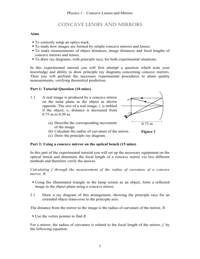
Physics 1 – Concave Lenses and Mirrors Concave LENSES AND MIRRORS Aims To correctly setup an optics track. To study how images are formed by simple concave mirrors and lenses. To make measurements of object distances, image distances and focal lengths of concave mirrors and lenses. To draw ray diagrams, with principle rays, for both experimental situations. In this experimental tutorial you will first attempt a question which tests your knowledge and ability to draw principle ray diagrams concerning concave mirrors. Then you will perform the necessary experimental procedures to attain quality measurements, verifying theoretical prediction. Part 1: Tutorial Question (10 mins) 1.1 A real image is produced by a concave mirror on the same plane as the object as shown opposite. The size of a real image, i, is trebled if the object, o, distance is decreased from 0.75 m to 0.50 m. o i (a) Describe the corresponding movement of the image. (b) Calculate the radius of curvature of the mirror. (c) Draw the principle ray diagram. 0.75 m Figure 1 Part 2: Using a concave mirror on the optical bench (15 mins) In this part of the experimental tutorial you will set up the necessary equipment on the optical bench and determine the focal length of a concave mirror via two different methods and therefore verify the answer. Calculating f through the measurement of the radius of curvature of a concave mirror, R. Using the illuminated triangle in the lamp screen as an object, form a reflected image in the object plane using a concave mirror. 2.1 Draw a ray diagram of this arrangement, showing the principle rays for an extended object transverse to the principle axis. The distance from the mirror to the image is the radius of curvature of the mirror, R. Use the vertex pointer to find R. For a mirror, the radius of curvature is related to the focal length of the mirror, f, by the following equation: 1 Physics 1 – Concave Lenses and Mirrors R = 2f 2.2 What is the focal length of your mirror? Calculating f through the use of the mirror equation. Using the same object as before, use a screen with a large aperture and form an image on this screen by reflection from the mirror. The mirror equation relates the focal length of a mirror, or lens, to the object and image distances as follows: 1 1 1 f s s' 2.3 Measure the object and image distances and hence calculate the mirrors focal length. Comment on your two results for focal length i.e. do they compare well. Part 3: Tutorial Question (10mins) 3.1 A thin diverging lens is placed on an optical bench. Parallel beams of light pass through the lens. On viewing the lens they appear as if they came from a point 20cm before the centre of the lens, as shown in figure 2. You want to use this lens to form a vertical virtual image that is a third of the height of the object. . 0.20 m (a) Where should the object be placed? (b) Draw a principle ray diagram. Figure 2 Part 4: Using a concave lens on the optical bench (15 mins) In this part of the experimental tutorial you will determine the focal length of a converging lens then observe the change when the same lens is used in conjunction with a diverging lens. Measuring this change accurately will enable you to calculate the focal length of the diverging lens. Select a converging lens and place it into the holder on the optical track. Use the illuminated triangle in the lamp screen as an object. Form a bright image on the object plane by reflection from a plane mirror on the opposite side of the lens from the object, as shown in Figure 4. 2 Physics 1 – Concave Lenses and Mirrors 4.1 What is the focal length of the convex lens? The power, P, of a lens is related to its focal length by the expression: P 1 , f where f is measured in metres, and the units of P are dioptres. 4.2 Calculate the power of this lens. Select the diverging lens and put it into contact with the converging lens. Place the plane mirror on the opposite side of the object as before and form an image in the object plane. This image may be fainter so it’ll be harder to spot, and the object/image distance will be larger. Beware of images formed by reflection, there will be two images formed by reflection from the lenses which you want to ignore. Use the method for combined lenses to obtain the power of the lenses in contact. Use PC = P1+P2 algebraically to calculate the power of the diverging lens. 4.3 Using your result for the power of the diverging lens calculate its focal length. Part 5: Diverging lens and concave mirror (Optional) Virtual Image Real Object O M I C L The virtual image I formed by the lens L is thus at the centre of curvature of the mirror Figure 3 5.1 On the optical bench set up the arrangement shown in figure 3; use a concave mirror of known radius of curvature. Hence take measurements to obtain the focal length of the diverging lens. Further work The following questions are related to the topic covered by this experimental tutorial. Exercise book questions L1- L16. 3 Physics 1 – Concave Lenses and Mirrors Mastering Physics: Optics 1 (parts 5 and 6); Optics 2 4 Physics 1 – Concave Lenses and Mirrors Demonstrators' Answers, Hints, Marking Scheme and Equipment List Marking Scheme Section 1.1a 1.1b 1.1c 2.1 2.2 2.3 3.1a 3.1b 4.1 4.2 4.3 Discretionary mark TOTAL Mark 0.5 1 0.5 1 1 1 0.5 0.5 1 1 1 1 10 Answers 1.1(a) The image moves away from the mirror. 1 1 2 1.1(b) s s' R 1 1 1 1 1 R 2 0.75 0.75 0.75 R 0.75 m 1.1(c) o i 0.50 m 2.1 See Figure 1. 2.2/2.3 They should be very similar; differences tend to arise due to rounding of numbers. 3.1(a) From the information given: m 1 s' 1 s , i.e. s ' , therefore 3 s 3 3 5 Physics 1 – Concave Lenses and Mirrors so substituting into and s' 0.133 m 1 1 1 1 1 1 gives so s 0.40 m s s' f s s 0.20 3 3.1(b) . . 0.20 m Part 4: The power obtained for the concave lens should be a negative value. Equipment List Concave mirror Concave lens Convex lens Plane mirror Light source Screen with triangular hole Pointer 3 x saddles 3 x holders 6 Physics 1 – Concave Lenses and Mirrors Example Numbers Part 2: Quantity r Pointer Measurement 1 (m) Pointer Measurement 2 (m) 0.571 0.734 Length of pointer (m) 0.2 f Length (m) 0.363 0.1815 s s' 0.571 0.866 0.934 0.934 0.2 0.2 f 0.563 0.268 0.1816 Part 3: Pointer Measurement 1 (m) Pointer Measurement 2 (m) Length of pointer (m) s1 0.571 0.698 0.2 0.327 s1' 0.571 0.698 0.2 0.327 Quantity f1 Length (m) 0.1635 s2 0.578 1.246 0.2 0.8680 s2' 0.578 1.246 0.2 0.8680 fc 0.4340 P1 (dioptre) Pc (dioptre) P2 (dioptre) 6.116208 2.304147 -3.81206 f2 -0.26233 7

