(摘自Principles of Physics第25章)
advertisement

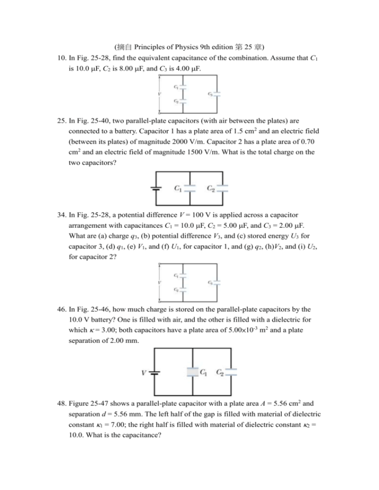
(摘自 Principles of Physics 9th edition 第 25 章) 10. In Fig. 25-28, find the equivalent capacitance of the combination. Assume that C1 is 10.0 F, C2 is 8.00 F, and C3 is 4.00 F. 25. In Fig. 25-40, two parallel-plate capacitors (with air between the plates) are connected to a battery. Capacitor 1 has a plate area of 1.5 cm2 and an electric field (between its plates) of magnitude 2000 V/m. Capacitor 2 has a plate area of 0.70 cm2 and an electric field of magnitude 1500 V/m. What is the total charge on the two capacitors? 34. In Fig. 25-28, a potential difference V = 100 V is applied across a capacitor arrangement with capacitances C1 = 10.0 F, C2 = 5.00 F, and C3 = 2.00 F. What are (a) charge q3, (b) potential difference V3, and (c) stored energy U3 for capacitor 3, (d) q1, (e) V1, and (f) U1, for capacitor 1, and (g) q2, (h)V2, and (i) U2, for capacitor 2? 46. In Fig. 25-46, how much charge is stored on the parallel-plate capacitors by the 10.0 V battery? One is filled with air, and the other is filled with a dielectric for which = 3.00; both capacitors have a plate area of 5.00×10⁻³ m2 and a plate separation of 2.00 mm. 48. Figure 25-47 shows a parallel-plate capacitor with a plate area A = 5.56 cm2 and separation d = 5.56 mm. The left half of the gap is filled with material of dielectric constant 1 = 7.00; the right half is filled with material of dielectric constant 2 = 10.0. What is the capacitance? 49. Figure 25-48 shows a parallel-plate capacitor with a plate area A = 7.89 cm2 and plate separation d = 4.62 mm. The top half of the gap is filled with material of dielectric constant 1 = 11.0; the bottom half is filled with material of dielectric constant 2 = 12.0. What is the capacitance? 50. Figure 25-49 shows a parallel-plate capacitor of plate area A = 12.5 cm2 and plate separation 2d = 7.12 mm. The left half of the gap is filled with material of dielectric constant 1 = 21.0; the top of the right half is filled with material of dielectric constant 2 = 42.0; the bottom of the right half is filled with material of dielectric constant 3 = 58.0. What is the capacitance? 51. A parallel-plate capacitor has a capacitance of 100 pF, a plate area of 100 cm2, and a mica dielectric ( = 5.4) completely filling the space between the plates. At 50 V potential difference, calculate (a) the electric field magnitude E in the mica, (b) the magnitude of the free charge on the plates, and (c) the magnitude of the induced surface charge on the mica. 61. Figure 25-54 shows capacitor 1 (C1 = 8.00 F), capacitor 2 (C2 = 6.00 F), and capacitor 3 (C3 = 8.00 F) connected to a 12.0 V battery. When switch S is closed so as to connect uncharged capacitor 4 (C4 = 6.00 F), (a) how much charge passes through point P from the battery and (b) how much charge shows up on capacitor 4? (c) Explain the discrepancy in those two results. 65. In Fig. 25-56, the parallel-plate capacitor of plate area 2.00×10⁻² m2 is filled with two dielectric slabs, each with thickness 2.00 mm. One slab has dielectric constant 3.00, and the other, 4.00. How much charge does the 7.00 V battery store on the capacitor? 66. A cylindrical capacitor has radii a and b as in Fig. 25-6. Show that half the stored electric potential energy lies within a cylinder whose radius is r = ab . 69. A certain capacitor is charged to a potential difference V. If you wish to increase its stored energy by 10%, by what percentage should you increase V? 77. In Fig. 25-59, two parallel-plate capacitors A and B are connected in parallel across a 600 V battery. Each plate has area 80.0 cm2; the plate separations are 3.00 mm. Capacitor A is filled with air; capacitor B is filled with a dielectric of dielectric constant = 2.6. Find the magnitude of the electric field within (a) the dielectric of capacitor B and (b) the air of capacitor A. What are the free charge densities on the higher-potential plate of (c) capacitor A and (d) capacitor B? (e) What is the induced charge density on the top surface of the dielectric? Ans. 10) 8.44 F 25) 3.6 pC 34) (a) 2.00×10⁻⁴ C (b) 100 V (c) 1.00×10⁻² J (d) 3.33×10⁻⁴ C (e) 33.3 V (f) 5.55×10⁻³ J (g) 3.33×10⁻⁴ C (h) 66.7 V (i) 1.11×10⁻² J 46) q1 = 6.64 1010 C, q2 = 2.21 1010 C 48) 7.52×10⁻¹² F 49) 1.73×10⁻¹¹ F 50) 5.42×10⁻¹¹ F 51) (a) 1.0×10⁴ V/m (b) 5.0 10–9 C (c) 4.1 nC 61) (a) 7.20 C (b) 18.0 C (c) The battery supplies charges only to the plates where it is connected. The charges on the rest of the plates are due to electron transfers between them, in accord with the new distribution of voltages across the capacitors. So, the battery does not directly supply the charge on capacitor 4. 65) 1.06 109 C 69) V / V = 4.9% 77) (a) 2.00 10 V/m (b) 2.00 10 V/m (c) 1.77 10 C/m2 (d) 4.60 10 C/m2 (e) –2.83 10 C/m2
![Sample_hold[1]](http://s2.studylib.net/store/data/005360237_1-66a09447be9ffd6ace4f3f67c2fef5c7-300x300.png)


