the balmer spectrum of atomic hydrogen
advertisement
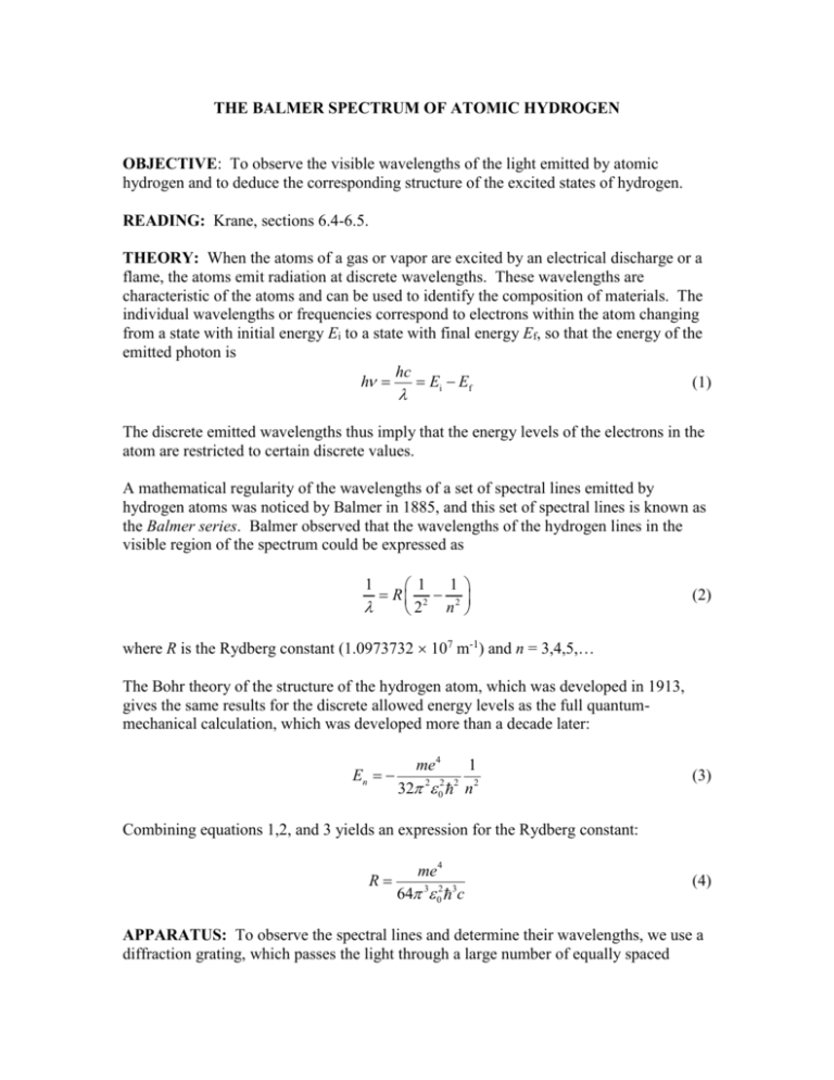
THE BALMER SPECTRUM OF ATOMIC HYDROGEN OBJECTIVE: To observe the visible wavelengths of the light emitted by atomic hydrogen and to deduce the corresponding structure of the excited states of hydrogen. READING: Krane, sections 6.4-6.5. THEORY: When the atoms of a gas or vapor are excited by an electrical discharge or a flame, the atoms emit radiation at discrete wavelengths. These wavelengths are characteristic of the atoms and can be used to identify the composition of materials. The individual wavelengths or frequencies correspond to electrons within the atom changing from a state with initial energy Ei to a state with final energy Ef, so that the energy of the emitted photon is hc h Ei Ef (1) The discrete emitted wavelengths thus imply that the energy levels of the electrons in the atom are restricted to certain discrete values. A mathematical regularity of the wavelengths of a set of spectral lines emitted by hydrogen atoms was noticed by Balmer in 1885, and this set of spectral lines is known as the Balmer series. Balmer observed that the wavelengths of the hydrogen lines in the visible region of the spectrum could be expressed as 1 1 R 2 2 2 n 1 (2) where R is the Rydberg constant (1.0973732 107 m-1) and n = 3,4,5,… The Bohr theory of the structure of the hydrogen atom, which was developed in 1913, gives the same results for the discrete allowed energy levels as the full quantummechanical calculation, which was developed more than a decade later: En me4 32 2 2 0 2 1 n2 (3) Combining equations 1,2, and 3 yields an expression for the Rydberg constant: R me4 64 3 02 3c (4) APPARATUS: To observe the spectral lines and determine their wavelengths, we use a diffraction grating, which passes the light through a large number of equally spaced parallel slits; the resulting pattern of interference maxima occurs when the light arrives in phase at the image plane. Bright light of the characteristic wavelengths (colors) can then be observed at those locations. The condition for constructive interference in first order is (5) d sin where d is the spacing between the slits and is the angle by which the light is deviated from its original path. The geometry of the experiment for observing the spectral lines with the grating is shown in Figure 1. Image of LED Diffraction grating Hydrogen discharge y tube y Camera lens Spectral lines Images of spectral lines LED D Figure 1 If the distance y of the spectral lines from the central axis of the apparatus were known, it would be possible to find from tan = y/D, where D is the distance between the diffraction grating and the object plane containing the H tube and the spectral lines. The spectral lines will be measured by photographing them with a digital camera and analyzing the resulting photo on a computer. Placing an LED in the object plane allows you to calibrate distances along the y direction. Knowing the distance y for the LED and determining the distance y by counting pixels on the photographic image gives the necessary calibration. By determining the distances y in pixels for the images of the spectral lines, you can deduce their locations y and then their angular locations . PROCEDURE: The hydrogen discharge lamp should not be left on for long periods. Turn it on only when needed for viewing or photographing the spectrum. Place the diffraction grating in front of the camera, oriented so that the spectral lines are spread horizontally. Align and focus the camera so that you can see all of the spectral lines on one side of the tube and as many as possible on the other side. Place the LED at a convenient location to give you a reliable calibration (making y for the LED as large as possible) but not to interfere with any of the spectral lines. Transfer the digital image to your computer and determine the locations in pixels of the spectral lines and the LED. From the known position of the LED, calculate the y coordinates of the spectral lines and determine the angle for each line. Average the results for identical lines on opposite sides of the axis and determine the best value for the wavelength of each line. Estimate the uncertainty in each measurement of the wavelength, including the error in determining the image position from the computer and other geometrical errors that may be part of the measurement. Knowing that the smallest value of n gives the largest wavelength, assign values of n to your measured wavelengths and plot 1/ vs. 1/n2. Determine the slope and intercept, and interpret. Use your estimated uncertainty in the wavelengths to place uncertainty limits on the slope and intercept. Determine the best value of the Rydberg constant R (and its uncertainty) from your data. QUESTIONS: 1. From the density of pixels on the digital image, can you make any conclusions about the relative intensities of the spectral lines? 2. Suppose we repeated this experiment with a helium discharge tube instead of hydrogen. In the Bohr model, the electrostatic force on the electron in hydrogen is e2/40r2, while in helium (Z = 2) the force is 2e2/40r2. Equation 2 applies only to hydrogen, but the transformation from hydrogen to helium can be accomplished, according to the force equations, by replacing e2 with 2e2. How many spectral lines in the Balmer series of helium would be in the visible region of the spectrum? Assume that the Balmer series in helium likewise involves the factor (1/22 – 1/n2) with n = 3,4,5,…
