MURI Book 2
advertisement
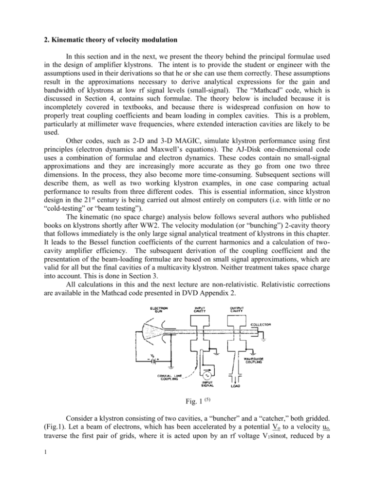
2. Kinematic theory of velocity modulation In this section and in the next, we present the theory behind the principal formulae used in the design of amplifier klystrons. The intent is to provide the student or engineer with the assumptions used in their derivations so that he or she can use them correctly. These assumptions result in the approximations necessary to derive analytical expressions for the gain and bandwidth of klystrons at low rf signal levels (small-signal). The “Mathcad” code, which is discussed in Section 4, contains such formulae. The theory below is included because it is incompletely covered in textbooks, and because there is widespread confusion on how to properly treat coupling coefficients and beam loading in complex cavities. This is a problem, particularly at millimeter wave frequencies, where extended interaction cavities are likely to be used. Other codes, such as 2-D and 3-D MAGIC, simulate klystron performance using first principles (electron dynamics and Maxwell’s equations). The AJ-Disk one-dimensional code uses a combination of formulae and electron dynamics. These codes contain no small-signal approximations and they are increasingly more accurate as they go from one two three dimensions. In the process, they also become more time-consuming. Subsequent sections will describe them, as well as two working klystron examples, in one case comparing actual performance to results from three different codes. This is essential information, since klystron design in the 21st century is being carried out almost entirely on computers (i.e. with little or no “cold-testing” or “beam testing”). The kinematic (no space charge) analysis below follows several authors who published books on klystrons shortly after WW2. The velocity modulation (or “bunching”) 2-cavity theory that follows immediately is the only large signal analytical treatment of klystrons in this chapter. It leads to the Bessel function coefficients of the current harmonics and a calculation of twocavity amplifier efficiency. The subsequent derivation of the coupling coefficient and the presentation of the beam-loading formulae are based on small signal approximations, which are valid for all but the final cavities of a multicavity klystron. Neither treatment takes space charge into account. This is done in Section 3. All calculations in this and the next lecture are non-relativistic. Relativistic corrections are available in the Mathcad code presented in DVD Appendix 2. Fig. 1 (5) Consider a klystron consisting of two cavities, a “buncher” and a “catcher,” both gridded. (Fig.1). Let a beam of electrons, which has been accelerated by a potential Vo to a velocity uo, traverse the first pair of grids, where it is acted upon by an rf voltage V1sint, reduced by a 1 “coupling coefficient” M. The latter modifies the voltage across the grids to produce the effective voltage modulating the electron beam. Expressions for the coupling coefficient M (always less than 1) will be derived later. The electrons in the beam enter the gridded gap with energy, 1 mu02 eV0 2 2-1 where the electron charge e does not carry its own negative sign. The electron energy is modified by the rf field at the gap and the following relationship can be written for the exit velocity u: 1 1 mu 2 mu02 eMV1 sin t 2 2 2-2 from (1) and (2), it follows, u u0 1 MV1 sin t V0 2-3 If we assume that V1<<Vo (which is a good assumption for the first cavity of a two-cavity klystron), then u u0 1 MV1 sin t 2V0 2-4 We consider, for now, that the first interaction gap is very narrow, and that we can neglect the finite transit time of the entering electrons. (Later we will inquire into the happenings within both interaction gaps). The electrons then enter, and leave the first gap at time t1, then drift for a distance l, and arrive at the center of the second gap at time t2. Then (invoking again the small-signal assumption V1/V0<<1), t2 t1 l t1 u l l lMV1 t1 sin t1 u0 2u0V0 MV1 u0 1 sin t1 2V0 2-5 or, in terms of phase, t2 t1 0 X sin t 2 2-6 Fig. 2 (5) where 0 = l/u0, and the dimensionless quantity X = MV10/2V0 is called the “bunching parameter”. Obviously, when X>1, t2 is a multivalued function of t1 , and there is electron overtaking (Fig 2). The quantity of charge leaving the buncher in the time interval t1 to t1 +dt1 is Iodt1, at t1 = 0, where Io is the beam DC current entering the buncher. This charge, after drifting, enters the catcher in the interval t2 to t2+dt2. If It (total current, dc and rf) is the current transported by the beam to the entrance to the catcher, then through conservation of charge, I o dt1 I t dt2 2-7 dt2 1 X cos t1 dt1 2-8 It I o /(dt2 / dt1 ) 2-9 We have, differentiating 2-6 From (7) and (8), can now write and, replacing dt2/dt1 by its value in Eq. 2-9 It 3 Io (1 X cos t1 ) 2-10 For X = 1, the current at the catcher becomes infinite, since by inspection of Fig. 2, the finite charge transported from the buncher at t1 = 0 arrives at the catcher in a zero time interval (dt2/dt1=0). To calculate It, one must then sum the absolute values of all current contributions to It from time segments t11, t12, etc, at the buncher as follows, 1 1 It I 0 .... 1 X cos t11 1 X cos t12 2-11 The current waveforms at the buncher are shown in Fig. 3 below. Note that at the lower values of X they are almost sinusoidal, but they become rich in harmonics at X = 1 and above. Fig. 3 (5) Now, since It is clearly a periodic function of ωt2, it can be expanded in a Fourier series, as follows, I t I o [an cos n(t2 0 ) bn sin n(t2 0 )] 2-12 1 the coefficients are given by, an 1/ 0 I t cos n(t2 0 )d (t2 ) 2-13 I t sin n(t2 0 )d (t2 ) 2-14 0 and bn 1/ 0 0 Using 2-6 and (7) above, we can now write 4 an I0 cos n(t 1 X sin t1 )d (t1 ) 1 X sin t1 )d (t1 ) 2-15 and bn I0 sin n(t bn is identically equal to zero, since the integrand above is an odd function of t1 . It turns out that the expression (15) for the an coefficients is also a representation of the Bessel functions of the first kind and nth order (Fig. 4). an 2 J n (nX ) 2-16 Fig. 4 (5) Therefore, the catcher rf current It can be written as the following series I t I 0 2 I 0 J n (nX ) cos n(t1 0 ) 2-17 1 The n = 1 harmonic (the fundamental) is simply, I1 2 I 0 J1 ( X ) cos(t 0 ) Re 2 I 0 J1 ( X )e j (t 0 ) 2-18 When X<1, the series 2-17 converges for all values of t2. For X=1, and X>1, there are discontinuities at various t2 values as shown in Fig 3 (which would disappear if space charge 5 were taken into account). The harmonic amplitudes correspond to the peaks of the Bessel functions (Fig. 4). (Recall Fig. 17 in Lecture 1, where the current It was a series of -functions and all harmonics were equal. In this case, they are almost equal). We can now calculate the output power from the fundamental (n = 1), using 2-16 and the maximum value of J1(X), which is 0.582 and occurs at X = 1.84. The output power is the product of the rf current I1 and the maximum voltage that can be developed across the output gap without reflecting electrons, which is the beam voltage V0. Both are peak values, so, Pout 1.16 Io Vo x 0.58I 0V0 0.58Pin 2 2 2-19 Consequently, for the two-cavity klystron, without space charge and with sinusoidal voltage modulation, the maximum efficiency is 58 percent. The above derivation is completely valid, even when there is electron overtaking. The small-signal approximation, used to formulate the expressions used in launching the velocity modulated beam into the drift space is not, employed beyond the buncher in arriving at the above result. As we shall develop in following sections, however, the effects of space charge and a number of other issues force a much lower efficiency in the two-cavity klystron case. The mathematics becomes too complex for the purposes of these lectures, but it can be shown that the use of a third cavity, or an additional 2nd harmonic cavity, or multiple cavities properly arranged, can produce I1/Io ratios as high as 1.8. In one case, a multi-cavity experimental klystron efficiency of 74 percent has been a result of such optimum bunching. The velocity modulation kinematic treatment above was first published (in the US) by D. L. Webster, a collaborator of Hansen and the Varians at Stanford. His 1939 Journal of Applied Physics article included, in addition to the “bunching” theory, a brief theory of “debunching,” i.e. an accounting of the effects of space charge on the velocity modulation process. Eugene Feenberg, a member of the wartime Sperry Gyroscope “Tube Development Laboratory,” developed the Webster theory into a considerably more detailed mathematical treatise, which included the addition of a third cavity to the original two-cavity klystron, and the first formulae for coupling coefficients and beam loading in gridded and ungridded klystron cavity gaps. The Feenberg “Notes on Velocity Modulation”1 are not easy reading and were never published. Some of his derivations subsequently appeared in books in the U.S. and abroad. The Feenberg theory and most of the books on klystrons published in the 1940’s and early 1950’s developed formulae for the design of klystrons that included the assumption that u0 c . However, with the original Ginzton/Chodorow megawatt Stanford klystron, relativistic beams have become rather commonplace in radar and accelerator klystrons and relativistic corrections are necessary in the design. The derivations that follow are not relativistic, but a table at the end of the chapter provides correction factors for all pertinent klystron parameters and variables. Fremlin, Gent et al, presented a detailed analysis of beam loading in 1946.2 At the time, klystrons were mostly two-cavity or reflex oscillators, and the calculation of start-oscillation current was critical to their design. Consequently, the thrust of the article was to present detailed calculations of beam loading and other losses. The early large signal bunching theory of Webster required the assumption of closely spaced gridded gaps. This is unacceptable for highpower klystrons, because of grid interception (higher start-oscillation current), as well as for the “extended interaction” cavities discussed later, where the electric field is far from constant across the gap. It is therefore important to define a coupling coefficient, M, as a function of the electric 6 field, and to also define the related beam-loading parameter Gb, which is related to the energy expended at the interaction gap in bunching the beam (or is released by the beam to an unloaded cavity and causes self-oscillation). Beam-loading formulae will be restated later, using spacecharge theory, and it will be shown that the kinematic and space-charge treatments arrive at the same important result, for small signals. The analysis below is Gent’s, simplified by Branch in a 1960 paper.3 The objective is to define M and to derive an expression for the power given up by the beam to the field at the cavity gap, from which Gb can be calculated. A strong magnetic confining field is assumed, with no radial electron motion allowed. The calculation below only considers on-axis electronic motion. Subsequently, both coupling coefficient and Gb will be averaged over the assumed cylindrically symmetrical beam. M is probably the most important parameter used in the design of a klystron because the klystron gain is a function of M2n (where n is the number of cavities), and because it is very sensitive to the beam diameter, which is never known precisely. Hence discrepancies in the calculated or simulated gain of a klystron can be usually traced to inaccuracies in M. We begin with the equation of motion of the electron in a gridded gap field Ez(z,t), defined as Ez ( z , t ) Em f ( z )e jt 2-20 where Em is the maximum value of the electric field in a cavity interaction gap that extends from z = 0 to z = d. The function f(z) is a “shape factor”. The maximum rf voltage across the gap is d V1 = E z ( z ) dz Em d 2-21 0 A parameter α (for small-signal <<1) will be used to define the depth of modulation in relation to the dc beam voltage V1 / V0 2-22 The acceleration of electrons entering the gap field is then d 2 z V1 e f ( z )e jt dt 2 d m 2-23 If the field in the gap were zero, and the electron velocity u0, the electron position after time t would be z = u0t. Since the rf modulation is small, we can write, approximately u0t z h( z ) We now introduce e = ω /u0 , the “beam propagation factor”. The function h(z) is indeterminate for our purposes and does not enter in the calculations that follow. Then (24) becomes, 7 2-24 t e z 2-25 Multiply now both sides of 2-23 by 2dz and obtain the derivative of the square of the velocity, as follows 2 V e dz d 2 z d dz 2 dt dt 2 1 f ( z )e jt dz 2 dt dt dt dt d m 2-26 Integrating from z = 0 to a distance z within the gap 2 V1 e dz 2 f ( z )e jt dz u0 2 d m0 dt z 2-27 Substituting (25) into (27), integrating to the end of the gap (z = d) and denoting the exit velocity by u, we have d V 1 m(u 2 u02 ) e 1 f ( z )e j e z dz 2 d 0 2-28 Now recall Eq. (2), reproduced below, 1 1 mu 2 mu02 eMV1 eVeff 2 2 2-29 which expressed the change in kinetic energy of an electron after going through a narrow gap, with a voltage V1 across it (time dependence omitted). V1, when modified by the coupling coefficient M, yields the “effective voltage” acting on the electrons. We now have an accurate expression for M. In a one-dimensional system it is, by (21), (28) and (29), The effective voltage is then, d Veff Ez ( z )e j e z dz 2-30 0 and, M (e ) 8 d 1 Ez ( z )e j e z dz V1 0 2-31 d E ( z )e j e z z M (e ) dz 0 2-32 d E ( z )dz z 0 Eq. (32) can be generalized by extending the integration over the entire z-axis. It can then be applied to 2-dimensional (gridless gap, such as that in Fig. 5, below) The coupling coefficient can then be written, Ee j e z z M (e ) dz E dz Veff V1 2-33 z In words, M is equal to the convolution of the axial electric field E(z) with the exponential ejez (the effective voltage) , divided by the voltage (integral of the field) across the gap. Note also, that if the field Ez(z) is a piecewise continuous function of z, it can be written in terms of the inverse Fourier integral, g (e ) 1 2 E ( z )e j e z z dz 2-34 which means that M can be also written in terms of the Fourier transform of the electric field M (e ) 2 g (e ) V1 2-35 For most cases, where the field can be computed exactly with codes such as SUPERFISH or MAFIA (see Chapter 10), and where the field is an even function of z, a very simple expression results. M (e ) E z cos e z dz 2-36 E dz z 9 Applying it to the case of a gridded gap with a constant field of magnitude Ez =V1/d between –d/2 and d/2 (and shifting the original origin), we obtain the well-known expression V1 Ez ( z )e j e z dz d 1 M ( e ) V1 d d 2 cos zdz e d 2 sin e d 2 e d 2-37 2 This calculation demonstrates the use of a simplified form for the coupling coefficient when the field of interaction is an analytic function of z. In computer simulations, the field of an extended interaction cavity can be determined by simulation, listed in Excel (for example) with cos(ez) and computed using Eq.(34) for symmetrical fields, and (31) for arbitrary field distributions. This is a much better method for calculating M, if the cavity interaction field is known in detail. Klystron engineers generally do not rely on 2-37 to design their tubes, but rather employ more accurate, two-dimensional models. To derive a 2-dimensional expression for the coupling coefficient in ungridded cylindrical drift tubes, one must: a) assume a certain electric field at the edge of the gap at r = a, computed from the detailed nature of the drift tube tips, or determined by simulation, and calculate M at r = a, b) from that boundary condition, compute M as a function of r throughout the interaction region, and c) average the coupling coefficient over the beam. Fig. 5 The gap field is defined as before, this time with an r-dependence: Ez (r , z , t ) Em f (r , z )e jt 10 2-38 and at r = a, Ez (a, z, t ) Em f (a, z )e jt 2-39 Various authors have amused themselves over the years computing coupling coefficients for round tips, knife-edge tips, square tips, etc. Warnecke & Guenard4 assume drift tubes ending in knife-edges to obtain the expression below for the field at the gap, at the drift tube radius a. E z ( a, z ) 1 d /2 V1 z 1 d /2 2-40 2 Using (31), M ( a, e ) d d 1 1 1 Ez (a, z )e je z dz V1 0 V1 0 d / 2 V1 z 1 d /2 2 e je z dz 2-41 With a good table of integrals, we obtain the most commonly used coupling coefficient at r = a, d M ( a, e ) J 0 e 2 2-42 In the absence of space charge and for field varying sinusoidally with time in a vacuum, Maxwell’s equations reduce to the wave equation, 2r , z Ez 1 2 Ez c 2 Ez 2 2-43 where c is the velocity of light. Substituting from (45), 2 Ez 2 Ez 2 Ez 11 2-44 we have, 2 Ez k 2 Ez 2-45 where k = /c. If the variation with z is as ejz, then, 2r Ez ( 2 k 2 ) Ez 2-46 Since, unlike in a closed waveguide, the axial electric field cannot be zero on axis at the center of the gap, the solution to (50) cannot be a J0, but an I0 Bessel function, which is not zero at r = 0 as J0 is. This means that >k (or that wave the phase velocity u is lower than c and the appropriate function is I0(r)ejz, with, 2 2 k2 2-47 Since the axial field is completely specified at the surface r = a, it can be described as a Fourier integral over , for any value of r inside that surface Ez (r , z , t ) e jt I 0 r I a g ( )e j z d 2-48 0 where, as before, but now as a function of r as well, 1 g (r , ) 2 E ( r , z )e z j z dz 2-49 Let us now find the effective potential (integral of the field experienced by an electron traveling with the beam velocity u0 at a radius r along a line parallel to the axis. Let the electron enter the gap at t = 0. Since t e z , the electric field at r, z is I 0 r j ( ) z I 0 a g (r , )e e d Ez (r , z ) 2-50 Let us now integrate over z , at an arbitrary radius r to obtain the effective potential Veff, as in Eq. (33). Veff I0 r g ( r , )e j ( e ) z d I a 0 dz We will now use the following identity: 12 2-51 e j ( e ) z dz 2 ( e ) 2-52 The “delta function” ehas the property that, when multiplied by another function of , and integrated over from minus to plus infinity, it returns that function evaluated at e. Consequently, I0 r I r j ( e ) z dz g ( r , )e d 2 0 g (r , ) ( e )d I a I a 0 0 Veff 2-53 and, 2 I0 r I a g (r , ) ( e ) d 2 0 I0 e r g (r , e ) I 0 e a 2-54 where, e2 = e2 – k2. Then, Veff (r , e ) 2 g (r , e ) I 0 e r I0 e a 2-55 and M (r , e ) Veff (r , e ) V1 2 I r 1 g (r , e ) 0 e V1 I 0 e a 2-56 where, e2 e2 k 2 2-57 We will now drop the “e” subscript for from this point on, with the understanding that will always be represented by Eq. 2-57 and will always be real, where klystrons (or TWTs) are concerned. On the other hand, it is conventional in most textbooks to keep the subscript “e” in e = ω/u0. Now, evaluating Veff at r = a, and comparing with (35) and (42) M (r , e ) J 0 ( 13 e d I0 r ) 2 I0 a 2-58 which is the general expression for the coupling coefficient at radius r inside a gridless cylindrical gap of radius a and width d. Note that the total coupling coefficient M is the product of the coupling coefficient Ma at r = a, and M which represents an averaging of the coupling coefficient over the beam crosssection. If, instead of obtaining (42) from an analytic expression of the axial electric field at r = a, we obtained that field by simulation and used (33) to calculate a coupling coefficient at r = a, we would multiply the result with a calculated M . More generally, then M M a M J 0 ( e d / 2) I 02 ( b) I12 ( b) I 0 ( a) M I 02 ( b) I12 ( b) I 0 ( a) 2-59 Some typical numbers for the parameters used in evaluating M: If ed =1, a = 1 and b/a = 0.6, we obtain Ma = 0.765, M = 0.69 and M = 0.53. To conclude, we need to provide a formula for the beam loading conductance Gb. Recall that in Eq. (25) above, terms in were not included in the derivation of M. It turns out that calculation for beam loading requires these to be taken into account, and the derivation of an expression for Gb becomes very cumbersome. We will state the result below and explain it qualitatively 2 Gb e M G0 4 e 2-60 Equation (60) is quite general and applies to all gap shapes, as well as to the “extended” or “sheet beam” cavities that will be discussed later. Its meaning is that the ratio of the beam loading conductance Gb and the beam conductance G0 = (I0/V0) is entirely determined by the coupling coefficient M and its variation with the DC beam voltage. In the next lecture, we will see that the magnitude of the coupling coefficient M in extended cavities is optimized by synchronizing the phase velocity of the extended cavity to the beam velocity, and that the stability of these cavities depends on a positive Gb/G0 Using (60) with 2-37 and a little differential calculus, will verify the beam loading formula for plane gridded gaps, Gb 1 sin e d / 2 sin e d / 2 cos e d / 2 G0 2 e d / 2 e d / 2 2-62 14 2-61 If the expression (58) for M were manipulated as in Eq. (61) to obtain Gb/Go for the cylindrical non-gridded geometry, and the result were then averaged over the beam, a very complicated expression for beam loading results4. It is used in the Mathcad small-signal code (Section 4) since it is a closed expression and does not require a simulation of the field, but assumes the same gap geometry as Eq. 2-59 does. d d d I ( b) 2 I12 ( b) 1 2 d Gb / G0 e J1 e J 0 e M 2 J 0 2 e a 1 M 2 2-63 2 I a I a ( 1) 2 2 2 4 0 0 Where M is given by Eq. 2-59 A klystron cavity equivalent circuit, including the beam loading conductance (and susceptance) is shown in Fig. 5 below. A value for Bb is provided in the Warnecke book. It involves some drastic approximations and usually provides a very small correction to the very cavity inductance L. Fig. 6 A plot of Gb/Go is shown on Fig. 7 below. It is taken from the Warnecke & Guénard book, where the normalized parameters in terms of the usage here are: a′= b and b′= a. Note that Gb becomes negative at approximately ed/2 = 2.3 radians. The figure shows values of Gb for the beam filling the drift tube (solid lines) and for a 50% filling factor (dotted). Fig. 8 15 A simplified case of the normalized beam loading susceptance is shown above (Feenberg and Warnecke) It has been derived with the assumption that the gap is very short (d→0) and that the beam fills the drift tube. It is plotted against a (b′) for a pencil beam (solid plot) and a sheet beam (dotted, where a is half the narrow dimension of the drift tube) 16 1 2 Feenberg, E., “Notes on Velocity Modulation,” Sperry Gyroscope Lab. Report 5521-1043, Sperry Gyroscope Co., Inc., Garden City, NY, Sept 25, 1945. Fremlin, J. H., A. W. Gent, D. P. R. Petrie, P. J. Wallis, and S. G. Tomlin, “Principles of Velocity Modulation,” IEEE Journal 93, Part III A (1946) Pg. 875-917. 3 Branch, G. M. Jr., “Electron Beam Coupling in Interaction Gaps of Cylindrical Symmetry,” IRE Trans. on Elec. Dev., May, 1961, Pg 193-206. 4 Warnecke, R., and P. Guénard, Les Tubes Électroniques à Commande par Modulation de Vitesse, Paris: Gauthier Villars (1959). 5 Gewartowski, J. W., and Watson H. A.,Principles of Electron Tubes, D. Van Nostrand Company, Inc. 1965. 17
