Chapter 14
advertisement
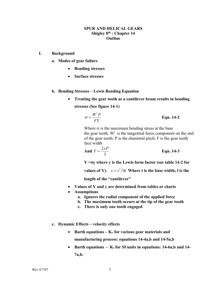
SPUR AND HELICAL GEARS Shigley 8th : Chapter 14 Outline I. Background a. Modes of gear failure Bending stresses Surface stresses b. Bending Stresses – Lewis Bending Equation Treating the gear tooth as a cantilever beam results in bending stresses (See figure 14-1) W tP FY Eqn. 14-2 Where is the maximum bending stress at the base the gear tooth. Wt is the tangential force component on the end of the gear tooth; P is the diametral pitch; F is the gear tooth face width 2xP And Y Eqn. 14-3 3 Y =y where y is the Lewis form factor (see table 14-2 for values of Y). x t 2 4l Where t is the base width; l is the length of the “cantilever” Values of Y and y are determined from tables or charts Assumptions a. Ignores the radial component of the applied force b. The maximum tooth occurs at the tip of the gear tooth c. There is only one tooth engaged c. Dynamic Effects – velocity effects Barth equations – Kv for various gear materials and manufacturing process: equations 14-4a,b and 14-5a,b Barth equations - Kv for SI units in equations: 14-6a,b and 147a,b. Rev 4/7/07 1 Equation 14-2 adjusted for velocity factor K vW t P FY Eqn. 14-7 The metric version K vW t FmY Eqn. 14-8 Where F and m are in mm; W t in Newtons gives in Mpa Face width F should be 3 to 5 times the circular pitch p Example 14-1 d. Surface Durability - Surface contact stresses applied to gears (1 / r1 ) (1 / r2 ) Wt Eqn. 14-11 2 F cos [(1 1 ) / E1 ] [(1 2 2 ) / E 2 ] 2 C Where c is the surface compressive stress. At the pitch lines of the teeth: r1 d p sin 2 and r2 d G sin 2 E’s are the Elastic constants of 1 and 2; F is face width ’s are Poisson’s ratio; dp and dG are pitch diameters AGMA elastic coefficient Cp 1 Cp [ ( 1 p Rev 4/7/07 Ep 1 G ) EG 2 1 2 Eqn. 14-13 Final compressive stress equation (including Kv) c C p [ 2 ] K vW t 1 1 12 ( )] F cos r1 r2 Minus sign since C is compressive See example 14-3 2 Eqn. 14-14 e. AGMA Stress Equations AGMA Bending stress equation 14-15 W t Ko Kv K s Pd K m K B (U. S. Customary Units) F J W t Ko Kv Ks 1 KH KB bmt YJ (S I Units) Where Ko is the overload factor; Ks is the size factor; Pd is the transverse diametral pitch; F(b) face width of narrower gear; Km (KH ) load distribution factor; KB is the rim-thickness factor; J (YJ ) is the geometry factor for bending strength (including root fillet stress concentration factor K f ). AGMA Pitting Resistance Equation (contact stresses) 14-16 C [W t K o K v K s K m C f 12 ] (U. S. Customary Units) dpF l C Z E [W t K o K v K s K H Z R 12 (S I Units) ] d w1b Z l Where Cp (ZE) is an elastic coefficient, lb f / in 2 ....( N / mm 2 ) Cf (ZR) is the surface condition factor; dp (dw1 ) is the pitch diameter of the pinion, in. (mm) I (Zl ) is the geometry factor for pitting resistance Factors explained in later sections AGMA Strength Equations AGMA Allowable Bending Stress (Equation 14-17) all all S t YN S F KT K R FP YN S F Y YZ (U. S. Customary Units) (S I Units) 1. AGMA Allowable Contact Stress (Equation 14-18) Rev 4/7/07 3 C , all all SC Z N CH S H KT K R (U S Customary Units) HP Z N ZW S F Y YZ (S I Units) S C ( HP ) are the allowable contact stresses lbf/in2 (N/mm2) ZN Stress cycle life factor CH (ZW) are the hardness ratio factors for pitting resistance KT (Y) are the temperature factors KR (Y Z ) are the reliability factors SH is the AGMA factor of safety, a stress ratio Values of S C are shown in figure 14-5 and tables 14-5 and 14-6 f. Geometry Factors I and J (ZI and ZJ) For Spur gear J factors see figure 14-6 For Helical gear J factors see figure 14-7 and 14-8 Surface geometry factors I (Z ) I cos t sin t mG (external gears) Eqn. 14-23 2mG mG 1 I cos t sin t mG (internal gears) Eqn. 14-24 2mG mG 1 Where mG NG dG NP dP Eqn. 14-22 and mN from Eqn 14-21( mN is 1 for spur gears) mN PN 0.95Z Eqn. 14-21 Where Z is given by eqn.14-25 g. The Elastic Coefficient CP ( ZE) Rev 4/7/07 4 See table 14-8 h. Dynamic Factor Kv Use figure 14-9 i. Overload Factor Ko j. Surface Condition Factor -- Use 1 k. Size factor Ks K S 1.192( F Y 0.0535 ) P Load Distribution Factor Km (KH ) a. See section 14-11 l. Hardness Ratio Factor CH See figures 14-12 and 14-13 m. Stress Cycle Life Factors Y and Z See figures 14-14 and 14-15 n. Reliability Factor KR (YZ ) Table 14-10 o. Temperature Factor KT ( Y ) Use KT ( Y ) =1.0 p. Rim Thickness Factor KB Backup Ratio a. m B tR ht b. See figure 14-16 Rim Thickness Factor Eqn 14-40 K B 1.6 ln( KB 1 Rev 4/7/07 2.242 ) mB 1.2 mB mB 1.2 5 q. Safety Factors SF and SH Definition of S F SF S t YN /( K t K R ) fully.corrected .bending .strength bending .stress Definition of S H SH S C Z N C H /( K T K R ) C fully.corrected .contact.strength contact.stress r. Analysis Rev 4/7/07 See figure 14-17: Road map for Spur gear bending See figure 14-18: Road map for Spur gear wear Example 14- 4 Example 14-5 6
