Vacuum measurement
advertisement
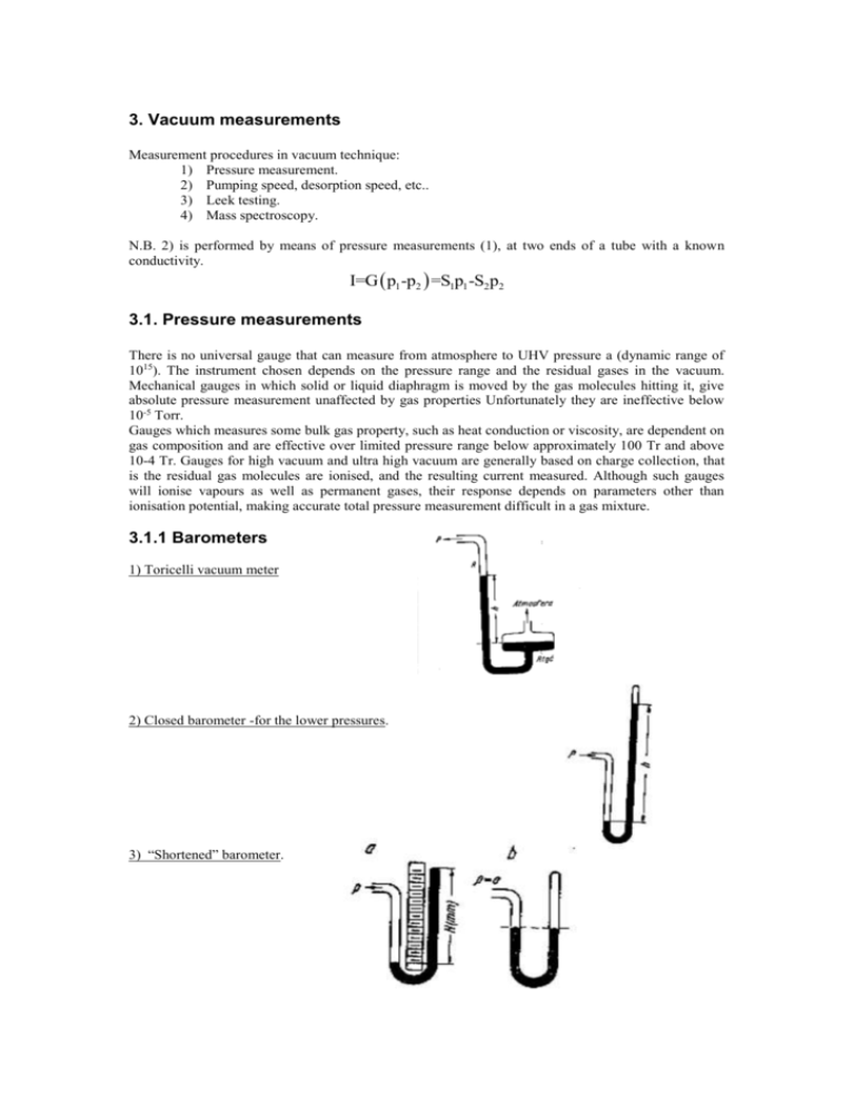
3. Vacuum measurements Measurement procedures in vacuum technique: 1) Pressure measurement. 2) Pumping speed, desorption speed, etc.. 3) Leek testing. 4) Mass spectroscopy. N.B. 2) is performed by means of pressure measurements (1), at two ends of a tube with a known conductivity. I=G p1 -p2 =S1p1 -S2p2 3.1. Pressure measurements There is no universal gauge that can measure from atmosphere to UHV pressure a (dynamic range of 1015). The instrument chosen depends on the pressure range and the residual gases in the vacuum. Mechanical gauges in which solid or liquid diaphragm is moved by the gas molecules hitting it, give absolute pressure measurement unaffected by gas properties Unfortunately they are ineffective below 10-5 Torr. Gauges which measures some bulk gas property, such as heat conduction or viscosity, are dependent on gas composition and are effective over limited pressure range below approximately 100 Tr and above 10-4 Tr. Gauges for high vacuum and ultra high vacuum are generally based on charge collection, that is the residual gas molecules are ionised, and the resulting current measured. Although such gauges will ionise vapours as well as permanent gases, their response depends on parameters other than ionisation potential, making accurate total pressure measurement difficult in a gas mixture. 3.1.1 Barometers 1) Toricelli vacuum meter 2) Closed barometer -for the lower pressures. 3) “Shortened” barometer. 4) Mechanical membrane gauge. 5) Compressing absolute barometer (McLeod) Fig: 7a insert figure: Operation principles: Bring the Hg level in the compression capillary 1 to y-y. The Hg level in the reference capillary 2, identical to 1, will be higher, at the line z-z. Equilibrium condition: p2=H+p1 in [Tr] units, where H is the difference between the Hg levels in 1 and 2. The compression ratio, k=V 1/V2, is set by the ration of the volume of the container 3 (V1 , known and constant for a given gauge) to V2=(/4)d2h.. In the equilibrium conditions p1V1=p2V2, i.e., V2 πd 2 h p1 = (H+p1 )= (H+p1 )=ch(H+p1 ) V1 4V1 p1 = where c= chH 1-ch πd 2 is the gauge constant. Typically ch 4V1 1 , and the measured pressure p1 chH In the linear method (case a, see figure) we keep the level difference constant h=h0. Then: p1 = ch 0 H c1H 1-ch 0 In the quadratic method (case b) we compress to have H=h, and p1 = cH H c2 H 2 1-cH We want the compression ration k to be as high as possible, therefore we want d to be as small as possible, but there is an obvious limit to reducing d. The best realistic k 104-105, allowing for measuring down to p 10-6 Torr. N.B. This is an absolute pressure gauge - important for calibration of relative vacuum meters. The gauge can operate either with mercury or with vacuum oil. There is a problem of contamination by the measuring agent and false effect due to the pumping by liquid. N 2 traps located at the system input. Reduced rotary McLeod – see Edwards catalogue 3.1.2. Thermomolecular Principle of operation Fig 7b Insert figure S - static plates are heated to T’, R - rotary plates at T In an ideal vacuum the plates would remain parallel. At the presence of the gas in-between the plates, the difference in velocity of molecules scattered from the hot plates and from cold gauge walls generates a torque momentum. From the side of the static plates the force /unite surface of a R plate is Fs =2m0 v`f1`=2c3n1m0 v`v From the opposite side, the R plates feel the force: Fb =2m0 vf1 `=2c3n1m0 v 2 The net force: v` T` ΔF=2c3n1m 0 v 2 -1 =p -1 v T p=cΔF=c`α The constant depends on the type of the gas through the accommodation coefficient (depending also on the state of the surface). The coefficient accounts for thermal energy transfer - non-perfect scattering. A particle scattered from the surface at temperature T does not fully accommodates the speed corresponding to that temperature. For heavy molecules 1. For light molecules 0.3 -- 0.4 (dirty surface) For light molecules 0.1 (for H2) -- 0.03 (for He) (clean surface) Measuring range is limited by : On the low pressure the limiting factor is electromagnetic radiation. p lim10-6 Torr On the high pressure the limiting factor is the viscosity of gas. p lim 10-1 Torr. 3.1.3. Friction gauge Fig. 7c. Gas molecules execute torque momentum on the measuring disk. The torque transfer efficiency depends on the gas pressure. The pressure is measured by examining the torque applied on the upper disk. In some gauges the discs are magnetically suspended. Pressure range: 10-2 - 10-6 Torr 3.1.4. Heat conductivity meters (Pirani) Heat conductivity of a gas depends on its pressure (through the number of molecules) The basic idea is shown in Fig 7d: Current carrying Pt or W wire (D) changes its resistance with changing temperature: R T R 0 1 T 1 1 β Pt =3×10⁻³ , β W =4.5×10⁻³ K K If the current through the wire is kept constant then the voltage drop VI I 0 R T will be a measure of the pressure. That is a constant current gauge. The opposite case: the voltage is maintained constant by adjusting the bias current (which is a measure of the pressure). That is a constant resistor gauge. Power delivered to the wire P I 0 R T I 0 VT is dissipated by: 1) gas 2) radiation 3) through the wire holders For low-pressure 2) and 3) start to dominate and set the measurements limit. 2 The relation V=f(p) is obtained from the calibration curve. In the laboratory practice the calibration is obtained by setting: V to V min (beginning of the csale) at p=760 Tr and V to Vmax ,(full scale) at p=0. p=0 in practice means p<10 -5 Tr – e.g., an operating diffusion pump. Zoology of heat conductivity meters: 1) constant current 2) constant resistance 3) thermistor 4) thermocouple 5) bimetal (mechanical read-out) 3.1.4.1. Thermocouple meter insert figure The pressure range between 10 and 10-3 Torr is indicated by measuring the voltage of thermocouple spot welded to a filament exposed to system gas. The filament is fed from a constant current supply, though its temperature depends on thermal losses to the gas. At higher pressure, more molecules hits the filament and remove more heat energy’ causing the thermocouple voltage to change. These gauges are used extensively in fore-line monitoring and to provide the signal to automatically switch the main chamber from backing and high-vacuum pumps at the crossover pressure. 3.1.4.1. Pirani In a Pirani gauge two filaments, often platinum, are used as resistance in to arms of a Wheatstone bridge. The reference filament is immersed in a fixed gas pressure, while the measurement filament is exposed to the system gas. The current through the bridge heats both filaments. As in T/C gauge, gas molecules conduct heat away from the immersed filament and unbalance the bridge. Pirani gauges have roughly the same pressure measurement range as T/C gauge and are used in identical application, but generally provide faster response. 3.2. Ion vacuum-meters For pressures lower then 10-3 Tr all measurement are based on ionising gas molecules and measuring the ion current. Ionisation is achieved by radiation ( particle) accelerated electrons cold glow discharge N.B. Sensitivity depends on the type of gas through deferent ionisation efficiency No. of ions created by 1 electron along the path of 1 cm at the pressure of 1 Tr. If the gauge sensitivity for air is 1 then: He H2 N Air 5 3 2.5 1 N2 0.9 O2 0.9 CO 0.9 A 0.8 CO2 0.7 Hg 0.3 The gauge measures the ion current collected by the collector circuit. Measurements with ion gauges bear an error due to a spurious effect of pumping by ion adsorption in the gauge body. 3.2.1. Ionization gauge Bayard – Alpert head Insert figure Covers the range between 10-4 to 10-9 Torr, with gauge sensitivity from 5 to 20 Toor -1. B-A gauges are available with one or two filaments (the second acting as a spare) and with two filaments material: thoria-coated iridium, used in oxygen reach application and for ‘burn-out’ resistance if the gauge is dumped to atmospheric, and tungsten, used for lower cost and in residual gases containing halogen. B-A heads are available in naked and dressed version, see Fig 7f,g VA 100 - 150 Volts Vc -25 - -75 Volts Ie 10 A - 10 mA Gage constant k (Tr-1) k= I ion Iep , p= 1 I ion =sI ion kI e typically k 10 - 30 Tr-1 , therefore for for Ie 1 - 5 mA s 10 Tr/A. N.B. The ion current in a B-A head is about an order of magnitude smaller then the pressure in Tr. The B-A gauge’s lower pressure limit (10-9 Torr range) is caused by emission of the soft X-ray radiation generated by primary electrons hitting the anode. X-ray photons reaching the ion collector electrode release photoelectrons. The electron current due to photoemission is indistinguishable from the ion current of the positive ions collected by the collector electrode. Below 10 -9 Torr the photoemission current becomes a large enough fraction of the ion current to distort the pressure reading (for vacuum 10-12 Tr. we have to measure current of 10-13A!). Below 10-9 Tr the collector current is: σ I c =kI e p+σIe =kIe p 1+ kp where I e is the X-ray contribution. In order to have the measurement error < 10%: σ 0.1 kp Therefore, the low pressure limit for the B-A head: p min 10 σ , ~ 10-9Tr range. k Readhead gauge B-A head with extended measuring range: Redhead gauge equipped with an additional thin wire modulator electrode located within the anode, see Fig 7j. The procedure consists of taking take two measurements with different potential V M of the modulator: 1) Set VM =VA and measure Ic’ 2) Set VM =Vc and measure Ic’’ Assuming that the X-ray contribution to both measurement is the same I`c =k`Ie p+σIe and I``c =k``Ie p+σIe Obviously, k’>k’’ and p= I`c -I``c k`-k`` Ic Redhead low pressure limit falls into 10-11 - 10-12 Tr range. Other low pressure extended range gauges Groszkowski - screened collector protected by a tube against X-rays see Fig 7h. Helmer-Haynord - applies magnetic field and bends the ion beam towards the hidden collector Lafferty - magnetic field assisted ionisation + bending. Cold cathode glow discharge head (Penning) Low pressure limit -- problems with ignition and glow maintenance. Same solutions use spark plug to start. At the high pressure side the limiting effect is the arc discharge. Range - 5*10-3 - 5*10-7 Tr. 3.3. Mass spectrometry Partial pressure measurement - spectroscopy of the gas composition Separation of masses can be performed by : 1) magnetic field bending of a particle trajectory. 2) Cyclotron resonance . 3) Time of flight. 3.3.1. Magnetic field Emitter Collector R k H M 0U Solutions: H = constant R = constant M0U = constant M0U = constant 3.3.1.1. 180 mass spectrometer Insert graph: Typical spectra for air at 10-9 Tr: Spectra of DC 704 vacuum oil vapour. Insert graph H2 H2O CH4 N2+CO O2 Ar 2 18 16 28 32 44 R M0 R0 M 0 s1 s2 Resolution: S1 and S2 are the apertures of the emitter and collector boxes. Observe that we cannot reduce s 1 and s2 below certain limits because the overall sensitivity will decrease. Typically: M0 102 M 0 3.3.2. Omegatron The principle is based on a cyclotron resonance of charged gas molecules Insert picture Electric field between electrodes P1-P2 =Ecos(t), electrons- flow from cathode K to anode A along (x-x’ path.), Gas ions are created along x-x, and accelerated by the electric field, in the presence of magnetic field. The cyclotron resonance frequency: c eH m0 At the resonance condition ions move along opening spiral tracks and each the collector. The resolution m0 M0 eH 2 R 0 m0 M 0 2 Em0 The Omegatron is a simple and a small device, e.g., 20x20x20 mm. Typical parameters: Ie ~ A, H ~ 3000 Oe, E ~ 10 V/cm, w for 2<M 0 < 100 2.3 MHz to 43 kHz, M0 ~ 10-20 M 0 3.3.3.Time of flight mass spectrometer (without magnetic field) kA - ionisation by dc electron current . ab - acceleration of the ioos by dc voltage electrodes b-d and d-e biased with ac electric field in opposite phases C e d b a This type of mass spectrometer has low resolution. A k 3.3.4. Quadruple mass spectrometer. Build around four rods through which the ionised gas particles are flowing. Between each pairs of rods there is a voltage difference V0+Vcos(t). Analysis is performed at = const and at changing V/V0 ratio. Collector is reacted only by ions with a mass: M0~V/2 .3.5. Direct flight pulse spectrometer Square shape accelerating pulse; all particles acquire the same energy but due to difference in mass they have different time of arrival to the collector. Measurement of collector signal in time. Big complicated but good resolution: M0 >100 M 0 3.4. Leak detection. Leak detector = mass spectrometer tuned permanently to He + a pumping unit. (diffusion pump or TM based). The pumping unit has precise tuning of the pumping speed (throttle valve) in order to provide optimum measuring condition for various leaks. In-side vs. outside operation (sneezing) .

