Calculation of non
Explanation of non-linearity calculation
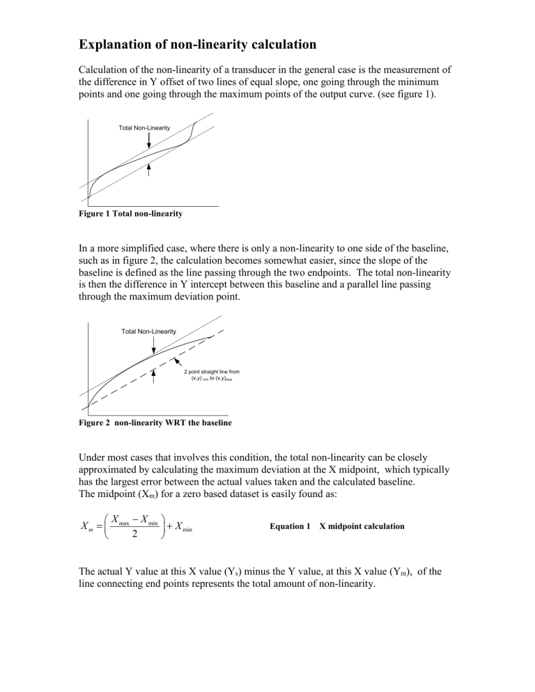
Calculation of the non-linearity of a transducer in the general case is the measurement of the difference in Y offset of two lines of equal slope, one going through the minimum points and one going through the maximum points of the output curve. (see figure 1).
Total Non-Linearity
Figure 1 Total non-linearity
In a more simplified case, where there is only a non-linearity to one side of the baseline, such as in figure 2, the calculation becomes somewhat easier, since the slope of the baseline is defined as the line passing through the two endpoints. The total non-linearity is then the difference in Y intercept between this baseline and a parallel line passing through the maximum deviation point.
Total Non-Linearity
2 point straight line from
(x,y) min
to (x,y) max
Figure 2 non-linearity WRT the baseline
Under most cases that involves this condition, the total non-linearity can be closely approximated by calculating the maximum deviation at the X midpoint, which typically has the largest error between the actual values taken and the calculated baseline.
The midpoint (X m
) for a zero based dataset is easily found as:
X m
X max
2
X min
X min
Equation 1 X midpoint calculation
The actual Y value at this X value (Y s
) minus the Y value, at this X value (Y m
), of the line connecting end points represents the total amount of non-linearity.
(X s
,Y s
)
Total Non-Linearity
(X m
,Y m
)
2 point straight line from
(x,y) min
to (x,y) max
X m
Figure 3 Midpoint non-linearity
% Linearity
y
max y
2 max y min
2 y
min
y min
y min
y s
100% Equation 2 General form
If the actual measured Y values pass through zero, this can be further simplified to be:
% Linearity
y max
2 y
max
y s
100%
Equation 3 Simplified form
2
