Supplementary information - Word file (22 KB )
advertisement

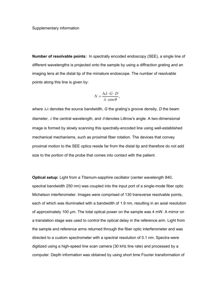
Supplementary information Number of resolvable points: In spectrally encoded endoscopy (SEE), a single line of different wavelengths is projected onto the sample by using a diffraction grating and an imaging lens at the distal tip of the miniature endoscope. The number of resolvable points along this line is given by: N G D , cos where denotes the source bandwidth, G the grating’s groove density, D the beam diameter, the central wavelength, and denotes Littrow’s angle. A two-dimensional image is formed by slowly scanning this spectrally-encoded line using well-established mechanical mechanisms, such as proximal fiber rotation. The devices that convey proximal motion to the SEE optics reside far from the distal tip and therefore do not add size to the portion of the probe that comes into contact with the patient. Optical setup: Light from a Titanium-sapphire oscillator (center wavelength 840, spectral bandwidth 250 nm) was coupled into the input port of a single-mode fiber optic Michelson interferometer. Images were comprised of 130 transverse resolvable points, each of which was illuminated with a bandwidth of 1.9 nm, resulting in an axial resolution of approximately 100 µm. The total optical power on the sample was 4 mW. A mirror on a translation stage was used to control the optical delay in the reference arm. Light from the sample and reference arms returned through the fiber optic interferometer and was directed to a custom spectrometer with a spectral resolution of 0.1 nm. Spectra were digitized using a high-speed line scan camera (30 kHz line rate) and processed by a computer. Depth information was obtained by using short time Fourier transformation of the measured spectra, resulting in ~20 axial resolvable points. The detection sensitivity was ~75 dB. Three-dimensional images were stored and displayed in real-time. Probe design: The distal optics of the SEE probe were assembled using transparent epoxy with a refractive index that was matched to that of the micro-optics to reduce reflections from optical interfaces. Light from a single-mode fiber, expanded through a 1.8 mm long silica spacer, was focused by a 350 µm diameter GRIN lens, and then diffracted by a 1000 lines/mm transmission grating (Holographix, Hudson, Massachusetts, USA) fabricated on a 1.5 mm long spacer that was polished at Littrow’s angle of 19°. The maximum diameter of the probe was 350 µm. This SEE probe had a field of view of approximately 2.6 mm and lateral resolution of 30 m FWHM, at 10 mm working distance. The confocal parameter was approximately 3.6 mm, and the angular field of view (angle between the shortest and the longest wavelength) was 15°. Probe rotation was accomplished by attaching the proximal end of the fiber to the shaft of a galvanometric scanner, which was scanned over a total angle of 40°. Ovarian cancer imaging in mouse: The murine model of disseminated ovarian cancer used in this study was developed by us previously (Molpus, K. L. et al. Characterization of a xenograft model of human ovarian carcinoma which produces intraperitoneal carcinomatosis and metastases in mice. Int J Cancer 68, 588-595 (1996)), and closely mimics the disease pattern seen in patients. The SEE probe was delivered into the abdominal cavity using a miniature laparaoscopic approach through a modified 23gauge hypodermic tube. A small opening was made in the tube wall, near its distal end, for the light to pass through. The opening was sealed with a clear 6-µm thick layer of transparent plastic.Insufflation of the abdominal cavity was performed using CO2 gas administered through a second 23-gauge needle. Note All experiments were reviewed and approved by the Massachusetts General Hospital Subcommittee on Research Animal Care (SRAC) — OLAW Assurance A3596-01.


![[sample] Focus Group & Individual Interview Guide](http://s3.studylib.net/store/data/006626260_1-52ac55bdb30beaa664c3c37fc5ba0cb1-300x300.png)


