parallel flow asymmetries due to non
advertisement

PARALLEL FLOW ASYMMETRIES DUE TO NON-UNIFORM
TEMPERATURES INVESTIGATED BY TRACER TECHNIQUES
R. Žitný and J.Thýn
Czech Technical University in Prague, Department of Process Engineering, Technická 4,
166 07 Prague 6 , CZECH REPUBLIC
Abstract. The effect of flow asymmetry was observed experimentally in lateral parallel channels of
continuous direct ohmic heater. While the flow in parallel channels is uniform at isothermal conditions, one
stream may be delayed and even stopped or reversed if the temperature differences between channels are
too high in case of heating. The effect can be explained by buoyancy and theoretical analysis predicts
existence of two solutions, symmetric and asymmetric distribution of flowrates, which can be stable within
a certain range of temperatures and flowrates. Integral model, based upon momentum and heat balances has
been suggested with the aim to predict influence of heater geometry, fluid properties and operational
parameters (flowrates, intensity of heating) upon the RTD of parallel laminar flows. The model takes into
consideration also the cross-flow between the main parallel streams. This “zonal” model enables to
calculate residence time distribution (RTD) of the heater and results predict that the effects of asymmetries
upon RTD is significant. Therefore the measurement of RTD characteristics seems to be promising method
for detection of the parallel flow asymmetries. Experimental verification was based upon a) flow
visualisation (injection of a coloured tracer and monitoring the tracer by Canon MV-100 camera), b)
measurement of temperature profiles (11 thermometers Pt100), and on c) stimulus response experiments
using KCl as a tracer for conductivity methods (2 Pt conductivity probes) and Tc99 as a radioisotope tracer
(collimated scintillation detectors). Results confirm predicted influence of operational parameters and
geometry (diameter of channels) on the stability of flow.
INTRODUCTION
Parallel flows are typical for many important apparatuses of process industries,
e.g. flows in shell&tube or plate heat exchangers, heaters, reactors. Sometimes flow
irregularities, instabilities or just only non-uniform distribution of flow in parallel
channels occur. These undesirable phenomena can be caused by natural convection if
the apparatus operates at non-isothermal conditions, which is typical for heat
exchangers or heaters.
Coloured
tracer
KMnO4
3
1
2
1
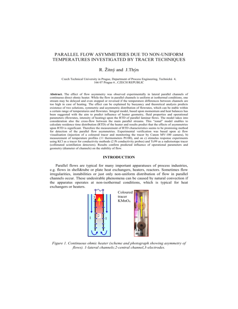
Figure 1. Continuous ohmic heater (scheme and photograph showing asymmetry of
flows). 1-lateral channels;2-central channel,3-electrodes.
The effect of flow asymmetry was observed experimentally in lateral parallel
channels of continuous direct ohmic heater, with two planar electrodes (electrical
current flows directly through the heated liquid), see Fig.1. Liquid enters the top of
heater and flows downwards through two rectangular channels where liquid is
preheated only by warm electrodes. At the bottom of heater the two parallel streams
join and liquid flows upward in a nearly uniform electrical field between electrodes
(distance 0.036 m, voltage 220 V, 50 Hz). In order to suppress the electrode fouling, a
perforation of electrodes was suggested, assuming that the cold cross-flow could
displace overheated substance moving slowly along the electrode surface.
While the flow in parallel channels is uniform at isothermal conditions, a
nonuniform distribution of flowrate and different temperature profiles exist in parallel
channels at heating and also the cross flow is changed. These phenomena can be
explained by the effect of buoyancy and can be detected by measuring of RTD.
STABILITY OF NON-ISOTHERMAL PARALLEL FLOWS
Parallel laminar flows in lateral channels of continuous ohmic heater are
symmetric only at isothermal conditions. In case of heating, one stream is delayed and
even stopped or reversed if the temperature increase is too high. This phenomenon
can be explained by buoyancy.
A similar situation occurs in a simpler and probably more frequent case
when two vertical parallel streams are separated by wall having a constant
temperature Te, see Fig.2.
pl(0) pr(0)
T0 Te T0
x
L
Ql
Insulation
Q-Ql
H
H
pl(L)= pr(L)
Tl(L) Tr(L)
Figure 2. Parallel flows heated by wall at constant temperature T e.
The analysis is based upon the fact that the pressure difference p(L)-p(0)
must be the same in the left and in the right channel at a steady state. We shall
consider only two contributions to the pressure difference: the first represents viscous
forces (written for flowrate Ql [m3.s-1] in the left channel)
p f (0) p f ( L)
12 Lf
Q
BH 3 l
(1)
where B, H [m] are dimensions of rectangular cross-section (depth and width of
channel respectively), and f equals 1 for laminar flow between plates or
f
1
192 H
1
nB
1 5
tgh 2 H
B n 1,3,5,... n5
(2)
for fully developed laminar flow in a rectangular channel B x H.
While the viscous component of pressure pf(x) decreases in the direction of flow,
the hydrostatic pressure pb(x) increases. Assuming linear temperature dependence of
density (coefficient proportionality [K-1]) and an exponential temperature profile
Tl(x),
B
x
Tl Te
c Q
e 0 p l
T0 Te
(3)
i.e. assuming a constant value of the heat transfer coefficient [W.m-2.K-1] and heat
capacity cp [J.kg-1.K-1], the contribution of hydrostatic pressure can be expressed as
L
pb (0) pb ( L) 0 g [1 (Tl T0 )]dx 0 gL{1 (T0 Te )[1
0
Ql 0 c p
BL
(1 e
BL
Ql 0c p
)]}
(4)
This expression can be approximated by
pb (0) pb ( L) 0 gL[1 (T0 Te )
BL
]
2Ql 0c p
(5)
for high heat capacity of stream Q0cp and for low value of heat transfer coefficient .
Summing pressure differences corresponding to the friction forces (1) and
buoayant forces (5) we can express equilibrium of forces in the left (lower index l)
and right (index r) channel by equation
12Lf
BL
12 Lf
BL . (6)
]
]
3 Ql 0 gL[1 (T0 Te )
3 Qr 0 gL[1 (T0 Te )
BH
2Ql 0 c p
BH
2Qr 0 c p
It is obvious that this equation is always satisfied by symmetric solution Ql=Qr ,
nevertheless another, asymmetric, solution can exist too
Ql Qr (Te T0 )
gB 2 H 3 L
24 fc p
.
(7)
Eq.(7) can be rearranged to a dimensionless form by introducing the total flowrate Q
and the ratio =Ql/Q
gB 2 H 3 L
(1 ) (Te T0 )
R
24 fc p Q 2
.
(8)
The Eq.(8) predicts, that the asymmetric solution (i.e. distribution of flowrates
satisfying balance of forces) can exist only if R<1/4. For higher values of
dimensionless parameter R the balance of forces cannot be satisfied giving rise flow
reversals or other form of flow instabilities.
An important question appears whether and when the symmetric and asymmetric
flow is stable. Let us assume a small disturbance of flowrate Ql+Q, Qr-Q, i.e.
slightly increased flowrate in the left channel and decreased in the right channel. Then
the pressure differences in the left and in the right channel are changed by increments
(see Eq.(6))
12 Lf
gBL2
12 Lf
gBL2
pl [
]Q,
pr [
]Q . (9)
3 ( Te T0 )
2
3 ( Te T0 )
2
BH
2Ql c p
BH
2Qr c p
In the case that pl>pl the pressure at the inlet to the left channel would be higher
than the pressure in the right channel and this difference induces transversal flow
towards the right channel. This redistribution of flow acts against the disturbance Q,
which means that the flowrates Ql,Qr will be stable if pl-pl>0 for Q>0, i.e.
24 fc p Q2
1
Q2 1
1
1 1
1
( 2 2) ( 2
).
2
3
R gLB H (Te T0 )
2 Ql Qr
2
(1 ) 2
(10)
This inequality leads to the conclusion that the symmetric flow (=0.5) will be stable
if
1
(11)
4.
R
Example, corresponding to the geometry of lateral channels of the direct ohmic heater
in Fig.1: B=0.08 m, H=0.008 m, L=0.56 m, flowrate of water Q=32 ml/s, =1000
kg.m-3, =0.00093 K-1, cp=4200 J.kg-1.K-1, =1 mPa.s, estimated =150 W.m-2.K-1.
Temperature difference Te-T0 calculated from (11) using these parameters is
approximately 10 0C, while flow asymmetries were observed within the range of
heating power 1.82.5 kW with corresponding water temperature increase 1318 0C
in experiments. The deviation between prediction (11) and experiment could have
been expected, because temperature of electrodes is not uniform and first of all is
lower than the temperature of heated water.
The inequality (10) can be used for assessment of asymmetric solution (8) as well:
1 1 1
1
1 2R ,
( 2
2)
R 2
(1 )
2R 2
R
1
4
(12)
In view of the fact that the asymmetric solution exists only for R<1/4, the stability
requirement R>1/4 cannot be satisfied and asymmetric solution cannot be stable.
ZONAL MODEL OF PARALLEL AND CROSS-FLOWS
Continuous heater with perforated electrodes exhibits also rather complicated
behaviour, because the cross flow through perforation is a decreasing function of
heating power. The reason can be also found in buoyancy effects.
Geometry of two lateral channels (denoted by indices l,r) and central channel
(c) is shown in Fig.3.
Tl0
p0
Qc1
pl1 Ql1 Tl1 Wl1
i-th layer
consists of
three cells,
l,c,r
Wr1 Qr1 pr1 L1
Tli-1 Wli-1
pli-1
Qli
Tli
pli
pli+1
Qli+1
Tli+1
Thi
Qci
Wli Tci
Thi+1
Qci+1
Wli+1 Tci+1
Qln Tln Wln-1 Qcn
Hc
Hl
pri-1
Li
Qri
pri
Tri+1 pri+1
h-width of slit
prn-1
prn
Ln
Hr
Figure.3.Zonal model
The following analysis is based upon integral balances of control volumes formed by
sections of heater between slits in perforated electrodes. It is assumed, that the flow
inside these volumes is fully developed, laminar and only in the axial direction.
Continuity equation can be written for each cell inside lateral channels
i 1
i 1
Qli Ql 0 Wlj
Qri Qr 0 Wrj
j 1
i=1,2,...,n
(13)
i=1,2,...,n
(14)
j 1
and for the central channel
i 1
Qci Qli Qri Ql 0 Qr 0 (Wlj Wrj )
j 1
Heat balance enables to estimate temperatures within the cells. Axial temperature
profiles in lateral channels are assumed continuous, while the axial temperature
profile are characterised by steps corresponding to injection of colder liquid in the
places where electrodes are perforated. The heater is assumed to be thermally
insulated therefore the balances of enthalpy in lateral channels give (written only for
the left channel as an example)
c p Qli (Tli Tli 1 ) l Li B(Tci Tli )
(15)
The axial temperature profile in the central channel is described by the step change at
the interface between control volumes (mixing with lateral streams, cross-flow)
Qci Tci Qci 1Thi 1 Wli Tli Wri Tri
(16)
while the temperature change inside the cell is given by
c p Qci (Thi Tci ) Li B[
l
2
(Tci Thi Tli Tli 1 )
r
2
(Tci Thi Tri Tri 1 ) i
U 2 (17)
]
Hc
where the last term describes volumetric heat source (i [S.m-1] is electrical
conductivity of liquid and U [V] voltage).
Pressure distribution is determined by hydraulic losses and by gravity. Hydraulic
losses and buoyancy can be calculated using the same method as previously, giving
axial profiles of pressure in lateral channels (written again for the left channel only)
pli pli 1 0 gLi [1 (
Tli 1 Tli
T0 )] Li f l Qli
2
i=1,2,...n
(18)
Tci Thi
T0 )] Li f cQci
2
(19)
and in the central channel
pci pci 1 0 gLi [1 (
where
fi
12 f
,
BHi3
i l, r , c .
(20)
Combining continuity equation with Eqs.(18-19) we can eliminate internal
pressures and express the pressure at an arbitrary cell in terms of pressure p0 at inlet
and volumetric flowrate Ql0 at inlet
i
pli p0 {0 gL j [1 (
Tlj 1 Tlj
j 1
2
j 1
T0 )] L j f l (Ql 0 Wlk )} .
(21)
k 1
Mention the fact that not only the inlet pressures, but also the pressures at the bottom
should be the same pln= prn, giving the following relationship between inlet flowrates
in the left and in the right lateral channel Ql0, Qr0:
0 g
2
n
n
j 1
j 1
j 1
k 1
L j (Tlj 1 Tlj Trj 1 Trj ) L( f r Qr 0 f j Ql 0 ) L j ( f lWlk f rWrk ) .
(22)
The crossflow is related to the pressure differences between lateral and central
channels. When calculating hydraulic resistance the two components are considered:
Pressure drop corresponding to viscous forces which is proportional to fw=12f/(Bh3)
and pressure drop corresponding to acceleration of liquid (Borda's losses):
pli pci
Wli2
2( Bh) 2
f wWli
(23)
This quadratic equation enables to express the flowrate as a function of pressure
difference
Wli
( Bh) 2
( f w
f w2
2 ( pli pci )
)
( Bh) 2
(24)
Iterative solution can be as follows: Flowrates at inlet (or ratio of flowrates
Ql0/Qc0) are selected as an initial approximation. Cross-flows Wli Wri are also
estimated, for example as zero. Flowrates in cells are calculated from continuity
equation (13-14). Knowing flowrates the complete temperature profiles are calculated
from (15-17). Pressures are calculated from Eq.(18-20) and (23), giving improved
values of cross-flow. New ratio of flowrates at inlet is calculated from Eq.(22), and all
previous steps are repeated several times.
This model forms a basis for development of spatially localised RTD
(Residence Time Distribution) model. Each cell in Fig.3 is described by a subsystem
of one to five ideally mixed tanks, and flow-rates at inlets to these subsystems
(including cross-flows) are given by preceding analysis. Thus it is possible to describe
the spatial distribution of concentration of tracer as a function of time. Initial
conditions (concentration of trace inside the heater) is zero, and inlet concentration at
entry to lateral channels can be an arbitrary function of time (delta function or
experimentally determined stimulus function). Resulting system of ordinary
differential equations is integrated numerically.
It is true that approximation of tracer dispersion in convective laminar flow by
a model formed by ideally mixed tanks is rather crude and cannot properly describe
details of flow near walls. However, the model is simple and comparison with
experiments indicates that the errors of calculated residence times are acceptable.
RTD EXPERIMENTS AND RESULTS
Experiments were performed with different thickness of lateral channels (Hl=Hr=
18, 11 and 7.8 mm). Temperature at lateral channels was recorded by two Pt100
probes and optical fibre probes Nortech TP-21-M02 which prove to be a sensitive
indicator of flow instabilities, however results have not completely evaluated yet.
Visualisation using KMnO4 as a colour tracer indicates that the asymmetric flow
could exist within a certain range of operational parameters, see the following table:
H [mm] Q [ml/s] Texper. [K]
8
76
20
8
65
22
8
39
31
18
83
14
18
72
17
18
68
18
Te-T0 Eq.(11)
58
42
15.3
14
10.3
9.2
Flow pattern
symmetric, stable
asymmetric
unstable
symmetric, stable
asymmetric ?
unstable
Evaluation
agree
acceptable
agree
acceptable
Eq.(11) unstable
agree
Residence time distribution was identified by using KCl and Tc-99 as a tracer [4].
Results obtained with these tracers are very similar, however the radioisotope is a
better tracer at heating because solution of Tc99 has no effect upon direct ohmic
heating (this is not true for solution of KCl which increases power and temperature
when passing between electrodes).
Selected results of RTD measured in the system with narrow and wide lateral
channels with and without heating and simulation by presented model for different
width of perforation h are shown in Figs. 4a, b, c and d.
P=0 kW, H=8mm
h: 1.20 1.26 mm
width of slits in
zonal model
P=0 kW, H=18mm
h: 1.2 1.4 mm
P=5 kW, H=8mm
h: 1.20 1.26 mm
P=5 kW, H=18mm
h: 1.1 1.3 mm
Figure 4. Experimental and simulated RTD for direct ohmic heater with perforated
electrodes with different width h of perforation. Conductivity method.
CONCLUSION
Buoyancy has undesirable effects in heaters with downwards oriented parallel
flows (non-uniform distribution and instability of flow), which can be suppressed by
Decreasing width of channels (this is the most efficient way)
Increasing viscosity
Cross-flow (perforation of walls) has also positive effect improving stability.
This research has been subsidized by the Research Project of Ministry of Education of the Czech Republic
J04/98:21220008
REFERENCES
[1] Žitný,R.,Šesták, J., Dostál M., Zajíček M., Continuous direct ohmic heating of liquids, International
Conference CHISA’98 , Prague, 23-28 August (1998)
[2] Žitný,R., Thýn, J., Verification of CFD predictions by Tracer Experiments, International Conference
CHISA’2000, Prague, 28 - 31 August (2000)
[3] Thýn, J., Žitný, R., Klusoň, J., Čechák,T.,Analysis and Diagnostics of Industrial Processes by
Radiotracers and Radioisotope Sealed Sources, Ed. ČVUT, Prague (1999)
[4] Žitný,R., Thýn, J.,Parallel flow asymetries in continuous heaters, CVUT Workshop 2001, Praha,
14-16 February (2001)


