INNOS-U32_HWitte_GOETHEX
advertisement
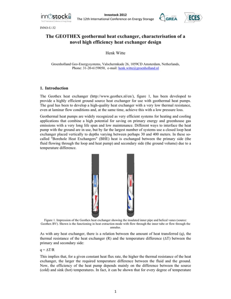
Innostock 2012 The 12th International Conference on Energy Storage INNO-U-32 The GEOTHEX geothermal heat exchanger, characterisation of a novel high efficiency heat exchanger design Henk Witte Groenholland Geo-Energysystems, Valschermkade 26, 1059CD Amsterdam, Netherlands, Phone: 31-20-6159050, e-mail: henk.witte@groenholland.nl 1. Introduction The Geothex heat exchanger (http://www.geothex.nl/en/), figure 1, has been developed to provide a highly efficient ground source heat exchanger for use with geothermal heat pumps. The goal has been to develop a high-quality heat exchanger with a very low thermal resistance, even at laminar flow conditions and, at the same time, achieve this with a low pressure loss. Geothermal heat pumps are widely recognized as very efficient systems for heating and cooling applications that combine a high potential for saving on primary energy and greenhouse gas emissions with a very long life span and low maintenance. Different ways to interface the heat pump with the ground are in use, but by far the largest number of systems use a closed loop heat exchanger placed vertically to depths varying between perhaps 30 and 400 meters. In these socalled "Borehole Heat Exchangers" (BHE) heat is exchanged between the primary side (the fluid flowing through the loop and heat pump) and secondary side (the ground volume) due to a temperature difference. Figure 1. Impression of the Geothex heat exchanger showing the insulated inner pipe and helical vanes (source: Geothex BV). Shown is the functioning in heat extraction mode with flow through the inner tube or flow through the annulus. As with any heat exchanger, there is a relation between the amount of heat transferred (q), the thermal resistance of the heat exchanger (R) and the temperature difference (ΔT) between the primary and secondary side: q = ΔT/R This implies that, for a given constant heat flux rate, the higher the thermal resistance of the heat exchanger, the larger the required temperature difference between the fluid and the ground. Now, the efficiency of the heat pump depends mainly on the difference between the source (cold) and sink (hot) temperatures. In fact, it can be shown that for every degree of temperature 1 Innostock 2012 The 12th International Conference on Energy Storage about 3% of efficiency is gained or lost in the heat pump. As the thermal resistance is one of the few properties that can be manipulated by the designer, this is a key parameter for BHE system design. For a system with a moderate specific heat flux (10 to 15 W/m borehole) the difference between a high efficiency and low efficiency design can be on the order of 5% on annual efficiency, for a system with a higher heat rate (30 to 50 W/m borehole) the difference in average efficiency can be up to 25%. To increase the heat transfer rate of a borehole heat exchanger, without increasing the temperature difference between fluid and ground, several options can be considered: 1) Increase the convective heat transfer between the fluid and the inside wall of the outside pipe. Especially in systems with laminar flow conditions (Reynolds < 2300) this is an important consideration. 2) Decrease the interaction (thermal loss) between the up flowing and down flowing pipe. 3) Increase the heat transfer between the borehole and the ground by enhancing the thermal conductivity of the borehole material or decreasing the borehole radius. One of the easiest ways increase the convective heat transfer is to increase the flow rate, but this also increases the pressure drop of the heat exchanger. This is especially true for borehole heat exchangers used for heating applications as the antifreeze used in these systems may have high viscosity at lower temperatures. In a concentric heat exchanger to attain turbulent flow in the annulus is especially difficult. The interaction between the up flowing and down flowing pipes can be decreased by using a low conductivity backfilling material and by using spacers in a U-loop type heat exchanger. In a concentric heat exchanger the resistance of the inner pipe wall can be increased. The choice of borehole backfilling can be limited by local environmental regulations, however the borehole quality and diameter are under the control of the driller. The selected drilling technique and depth can be optimized to provide production speed as well as high efficiency heat transfer. The Geothex heat exchanger has been developed to provide such a high efficiency heat exchanger. Together with a specially adapted drilling technique it promises to deliver high performance and high production rates at the same time. The basis of the Geothex heat exchanger is a concentric type heat exchanger, with a specially developed inner tube that has a higher thermal resistance. The outer wall of the inner tube has one or more helical vanes, that both centre the inner pipe and enhance heat transfer. A small diameter dry drilling technique has been developed for the installation of this heat exchanger. In this paper we present field and laboratory measurements of the thermal resistance and pressure loss of the Geothex heat exchanger. These measurements quantify the effect of the design on the thermal resistance and are used to provide corrected input parameters for borehole heat exchanger design software. 2. Material and methods The field test programme was conducted with a Thermal Response Test (van Gelder et al 1999, Witte et al 2002). In the test programme different Geothex heat exchangers and, for comparison, a standard U-loop heat exchanger were tested and compared. As the main interest was to measure the borehole resistance, the test duration was limited. The number of different operating conditions that can be tested with a field test are limited due to the waiting time between experiments. Also, the control of experimental conditions is not as good as in laboratory experiments. The basis of the laboratory experiment is that a steady state heat transfer between the fluid in the heat exchanger and the outer wall is achieved. From the temperature difference between the fluid and the outer wall, and the heat rate measured from the 2 Innostock 2012 The 12th International Conference on Energy Storage fluid flow rate and temperature difference between inlet and outlet, the thermal resistance can be directly calculated. To carry out the laboratory test, a section of heat exchanger was placed in a larger diameter tube (0.153 m diameter) of very thin sheet metal that was filled with medium size filter gravel. This assembly is a model of a borehole heat exchanger (figure 2), with horizontal dimensions equal to a real heat exchanger. The bottom and top of the heat exchanger were insulated to provide a known active length (typically 0.70 meters). K-type thermocouples were placed on the outside of the heat exchanger and on the outside of a simulated borehole while the fluid inlet and outlet temperature was measured with matched pair PT100 temperature sensors placed in the fluid flow. Flow rate was measured with a magnetic type flow meter. During the experiments data was collected at 30 sec. intervals using a Campbell CR1000 data logger system. Geothex Concentric HX U‐loop HX Thermocouples borehole wall Figure 2. Schematic of the Geothex heat exchanger (left) showing the insulated inner tube with a pitched ridge (not to scale) and standard U-loop (right) heat exchanger. Thermocouple positions are indicated, in the vertical three different positions were measured: near the top, end and middle The assembly was placed in a tank filled with water. The temperature of this tank was kept constant by continuous flushing with mains water. The thermal pulse was provided by the TRT machine, allowing heating and cooling pulses to be administered. For high quality measurements the calibration of the sensors is essential. The thermocouples were all constructed of the same batch of material and all were cut to the same length. All thermocouples were calibrated concurrently in an ice bath (in a vacuum flask), the sensor with the smallest measured standard deviation was selected as reference and for all other sensors a correction was calculated with respect to the reference, all correction factors are smaller than 0.1K and the average standard deviation is 0.037K. The 95% confidence interval of the temperature measurements is ±0.073K. the PT100 sensors were calibrated as well, the standard deviation after calibrating was 0.028K yielding a 95% confidence interval of ±0.055K. The error of the flow meter is < 0.2%. The thermocouples and PT100 sensors were used in one specific combination to calculate the following values: 1. The average fluid temperature Tf, calculated as the mean of the entering and exiting fluid temperature. This temperature is assumed to be representative of the average fluid temperature in the outer annulus of the concentric heat exchanger. 2. The average temperature on the outer wall of the concentric heat exchanger, calculated as the mean value of the thermocouple sensors fixed to the outer wall. For the U-tube heat exchanger this value is not used. 3 Innostock 2012 The 12th International Conference on Energy Storage 3. The average temperature on the borehole wall, calculated as the average of the thermocouple sensors fixed to the borehole wall. Measurements are taken every 30 seconds for a selected time period (with steady state heat transfer), for every sensor the average value and the individual error standard deviation is calculated from this data. The borehole and heat exchanger resistances are calculated as follows: Power rate Q (W/m): Q= q v * (T fin − T fout ) * C f 1 L Where: qv : Mean fluid flow m3/hr Tfin : Mean entering fluid temperature o Mean return fluid temperature o Tfout : C C Cf : Volumetric heat capacity of fluid J/m3 L : Length of the heat exchanger m Heat exchanger resistance Rhx calculated as the difference between fluid and heat exchanger wall temperature divided by the power rate: ⎛ n ⎜ ∑ Ttk T f − ⎜ tk =1 ⎜ n ⎜ ⎝ Rhx = Q ⎞ ⎟ ⎟ ⎟ ⎟ ⎠ 2 The borehole heat exchanger resistance Rbhe is calculated in the same way, only the thermocouple temperatures on the borehole wall are used instead of the temperatures on the heat exchanger wall. The error standard deviation of the temperature measurements is calculated by adding the individual error standard deviations in quadrature. The error standard deviation of the power rate is calculated by, the density and heat capacity are considered to be constant: ⎛ δq δQ = Q * ⎜⎜ v ⎝ qv ⎞ ⎟⎟ ⎠ 2 ⎛ δΔT f ⎜ ⎜ ΔT f ⎝ ⎞ ⎟ ⎟ ⎠ 2 3 The thermal resistance error standard deviation is calculated by: 2 ⎛ δT f ⎞ ⎛ δTtk ⎞ ⎛ δQ ⎞ ⎟ +⎜ ⎟⎟ + ⎜⎜ ⎟⎟ ⎟ ⎜ ⎝ T f ⎠ ⎝ Ttk ⎠ ⎝ Q ⎠ 2 2 δR = R * ⎜⎜ 4 Experiments were carried out with water as a fluid and with a 20% monopropylene mix. For both the laboratory experiments and field experiments the mixing ratio was determined by measuring temperature and density of the mix. The fluid properties were then taken at the bulk temperature during the experiment, the resulting error is very small (<2%, Witte 2012). The borehole resistance in the field experiments (Rbhe-TRT) was calculated as follows (Bruno et al 2011): 4 Innostock 2012 The 12th International Conference on Energy Storage Rbhe −TRT Q Tg ⎡ ⎡ ⎛ λ ⎢ 1 ⎢ ⎜4 H = (m − T g ) − ⎢ ⎢ln⎜ C 2 πλ Q 4 ⎢ ⎢ ⎜⎜ r0 ⎢⎣ ⎢⎣ ⎝ : : : : : : : : : λ H y r0 k C m ⎤⎤ ⎞ ⎟ ⎥⎥ ⎟ − γ ⎥⎥ ⎟ ⎥⎥ ⎟ ⎥⎦ ⎥⎦ ⎠ 4 Heat rate Far field (ground) temperature Ground thermal conductivity Ground loop length W/m o C W/mK m Eulers constant Borehole radius m Coefficient of the regression Tf with ln(t) K/ln(s) The ground thermal capacity J/(kgK) Is the intercept of the slope of the regression Tf with ln(t) K The thermal conductivity is estimated from the TRT data in the usual way (van Gelder et al. 1999). The error standard deviation of the borehole resistance in the field experiments is calculated by (Witte 2012): ∂Rb = ⎛ ΔRb ⎞ δH ⎟ ⎜ Δ H ⎝ ⎠ 2 ⎛ ΔRb ⎞ + ⎜ δλ ⎟ Δ λ ⎝ ⎠ ⎛ ΔRb + ⎜⎜ δQ ⎝ ΔQ 2 ⎞ ⎟⎟ ⎠ 2 ⎛ ΔRb ⎞ + ⎜ δC ⎟ Δ C ⎝ ⎠ ⎛ ΔRb ⎞ + ⎜ δm ⎟ Δ m ⎝ ⎠ 2 2 ⎛ ΔRb + ⎜ δTg ⎜ ΔT g ⎝ ⎞ ⎟⎟ ⎠ 2 ⎛ ΔRb + ⎜⎜ ∂ ro ⎝ Δ ro ⎞ ⎟ ⎟ ⎠ 2 5 During the experiment the reference sensor was kept in an ice bath in a vacuum flask, providing a reference temperature at 0 oC. Pressure drop was measured on a 45 and 20 meter long heat exchanger, at different flow rates and with water and monopropylene glycol (20%) as fluid. Moreover, pressure drop was measured on a head / footer assembly. In this way the pressure drop of the head and footer are known separately and the pressure drop over the heat exchanger can be calculated as pressure drop per meter. 3. Results Table 1 shows the different heat exchanger types tested, table 2 gives an overview of the different experiment parameters. The results of the first series of laboratory experiments was used to develop an improved version of the Geothex heat exchanger. Exchanger type Remarks Diameter Field BH 0.2 Outer pipe diameter (m) Inner pipe diameter (m) outer inner outer inner 0.0320 0.0260 - - - 0.0635 0.0544 0.0380 0.0190 2 U-loop Validation Geothex-I outer SDR 13.6 Geothex-IIa outer SDR 21 0.14 0.0630 0.0570 0.0380 0.0266 1 Geothex-IIb outer SDR 17 0.14 0.0630 0.0556 0.0380 0.0266 1 Geothex-IIc outer SDR 21 0.09 0.0630 0.0570 0.4450 0.0285 1 Geothex-III outer SDR 12.5 0.0630 0.0529 Table 1. Different heat exchanger dimensions, as measured on material. Vanes 5 Innostock 2012 The 12th International Conference on Energy Storage Boreholes for the field test were backfilled with Thermocem grout (thermal conductivity 2.0 W/mK). The first laboratory measurements were performed on a U-loop type heat exchanger, the purpose was to compare the calculated and measured borehole resistance and thereby validate the measurement process. The results (table 2) show a very good agreement between measured and calculated borehole resistance over a range of Reynolds numbers. Flow regime Reynolds number Measured Rb W/mK Calculated Rb W/mK Difference Laminar 1079 0.188 0.203 -0.015 Laminar 999 0.202 0.203 -0.001 Laminar 1264 0.222 0.203 0.019 Turbulent 2995 0.124 0.129 -0.005 Turbulent 3697 0.119 0.128 -0.009 Turbulent 3972 0.116 0.127 -0.009 Table 2. Laboratory measurement U-loop heat exchanger (validation). After the test on the U-loop heat exchanger the resistance of the prototype Geothex heat exchanger (with double vanes) was measured in three experiments. To obtain a better picture of the influence of the vanes the pressure loss was measured for a heat exchanger with double vanes, single vanes and no vanes (but with centred central tube). The results of the thermal resistance measurements are given in table 3, as an indication the Reynolds numbers are calculated for a standard concentric heat exchanger equivalent. The results of the pressure loss measurements (with water as circulation fluid) are shown in figure 3. The measured thermal resistances are clearly very low for all cases and do not depend on flow direction, the pressure losses on the other hand are high even at low flow rates. EXP 1 EXP 2 EXP 3 0.07 ± 0.010 0.280 ± 0.014 0.487 ± 0.020 Reynolds inner tube 1238 4786 8205 Reynolds annulus 254 984 1687 1.08 ± 0.041 0.35 ± 0.033 0.27 ± 0.027 133.20 ± 15.25 166.94 ± 17.58 221.78 ± 23.97 Tf , mean fluid temperature, C 26.00 ± 0.040 27.54 ± 0.053 25.73 ± 0.032 Thx, mean temperature heat exchanger wall, oC 19.07 ± 0.009 19.78 ± 0.008 19.01 ± 0.006 Rhx (K/(W/m)) 0.052 ± 0.006 0.046 ± 0.005 0.030 ± 0.003 Tbhe, mean temperature borehole wall, oC 11.48 ± 0.022 11.27 ± 0.026 11.35 ± 0.055 Rbhe (K/(W/m)) 0.109 ± 0.006 0.097 ± 0.005 0.065 ± 0.003 3 Flow (m /hour) ΔT fluid (K) Heat flux (W/m) o Table 3. Laboratory experiments Geothex I prototype heat exchanger thermal resistances. 6 Innostock 2012 The 12th International Conference on Energy Storage 1.80 1.60 Pressure loss (kPa/m) 1.40 1.20 No vane 1.00 Single vane 0.80 Double vane U-loop (32mm) 0.60 0.40 0.20 0.00 0.00 0.20 0.40 0.60 0.80 1.00 1.20 Flow (m3/hour) Figure 3. Pressure loss measurements Geothex I prototype, U-loop pressure loss indicated for comparison. Based on the experience with the Geothex prototype, the design was improved with regard to pressure loss and manufacturing process. Especially the number and pitch of the helical vanes was reduced and the insulating inner pipe was constructed in a different way (somewhat thinner wall with higher density). This new heat exchanger concept was then tested in a number of field and laboratory experiments. Here first the laboratory experiments and pressure loss measurements are presented. Table 4 shows the results of the thermal resistance measurements. In a first series of experiments (with the flow on the inner tube and return on the annulus) it proved very difficult to achieve steady state heat transfer, also the measured temperature difference was relatively small. With this setup the heat exchange between inner tube and annulus is maximal, and the laboratory tests are conducted with very high power rates. The flow rate was subsequently altered to flow to the annulus and return on the inner tube. Table 4 shows four typical results, two with water and two with 20% monopropylene glycol (increased viscosity). Overall measured thermal resistances are small. In some cases the total borehole resistance has a significant contribution to the overall thermal resistance, as the total resistance is larger than the resistance of the heat exchanger by itself (experiment 1, 3 and 4). Figure 4 shows the pressure loss measurements, for comparison the pressure loss of the U-loop heat exchanger and the prototype with single vane is included as well. Clearly this heat exchanger has a much lower pressure loss compared to the original prototype. The pressure loss at higher flow rates is still somewhat higher than the pressure loss for a U-loop heat exchanger. Final tests were the field tests carried out at the Geothex facility in Houten (Netherlands). Four different borehole heat exchangers were tested, length of the heat exchangers was around 45 meters. Average undisturbed ground temperature was measured in all heat exchangers, the average undisturbed ground temperature was 9.84 ± 1.77 oC. From the tests carried out the average thermal conductivity at the location was 2.05 ± 0.1 W/mK. This value is used for the calculation of the borehole resistance. A total of 12 experiments were carried out, the results are summarized in table 5. Field rest results are also shown ordered by Reynolds number in figure 5. 7 Innostock 2012 The 12th International Conference on Energy Storage Fluid 3 Flow (m /hour) EXP 1 EXP 2 EXP 3 EXP 4 H2O H2O 20% MPG 20% MPG 0.130 ± 0.011 0.573 ± 0.016 0.137 ± 0.019 0.316 ± 0.016 Reynolds inner tube 1488 6557 957 2207 Reynolds annulus 392 1727 252 581 0.72 ± 0.034 0.47 ± 0.030 0.739 ± 0.034 0.578 ± 0.033 149.59 ± 14.70 433.10 ± 30.40 158.41 ± 23.71 286.03 ± 21.78 Tf , mean fluid temperature, C 23.50 ± 0.061 33.82 ± 0.086 24.58 ± 0.016 32.00 ± 0.043 Thx, mean temperature heat exchanger wall, oC 15.18 ± 0.024 12.51 ± 0.018 13.68 ± 0.025 17.49 ± 0.043 Rhx (K/(W/m)) 0.056 ± 0.005 0.049 ± 0.003 0.069 ± 0.010 0.051 ± 0.004 Tbhe, mean temperature borehole wall, oC 10.46 ± 0.023 10.00 ± 0.013 9.82 ± 0.012 9.97 ± 0.022 Rbhe (K/(W/m)) 0.087 ± 0.005 0.055 ± 0.003 0.093 ± 0.010 0.077 ± 0.004 ΔT fluid (K) Heat flux (W/m) o Table 4. Laboratory experiments Geothex II heat exchanger thermal resistances. 1.60 Pressure loss (kPa/m) 1.40 1.20 1.00 Single vane Geothex II 0.80 U-loop (32mm) 0.60 0.40 0.20 0.00 0.00 0.20 0.40 0.60 0.80 1.00 1.20 1.40 Flow (m3/hour) Figure 4. Pressure loss measurements Geothex II heat exchanger, for comparison the pressure loss of the single vane Geothex prototype and U-loop heat exchanger are included. 8 Innostock 2012 The 12th International Conference on Energy Storage Experiment Q (m3/hr) Reynolds (annulus /inner) ΔT fluid (K) Heat flux (W/m) Borehole resistance (K/(m/W)) 1 U-loop 0.73 ± 0.02 5423 1.84 ± 0.14 34.09 ± 2.80 0.150 ± 0.01 2 U-loop 0.41 ± 0.02 1785 -1.69 ± 0.17 -17.32 ± 1.96 0.245 ± 0.01 3 GT IIa 0.32 ± 0.02 471 1638 -2.23 ± 0.20 -20.81 ± 1.66 0.165 ± 0.007 4 GT IIa 0.50 ± 0.02 736 2628 -2.38 ± 0.30 -31.64 ± 4.16 0.133 ± 0.007 5 GT IIa 0.73 ± 0.02 1478 5279 1.76 ± 0.16 34.09 ± 3.15 0.117 ± 0.007 6 GT IIb 0.31 ± 0.02 463 1626 -2.47 ± 0.19 -21.08 ± 2.53 0.137 ± 0.008 7 GT IIb 0.54 ± 0.02 808 2836 -2.49 ± 0.19 -37.03 ± 3.17 0.120 ± 0.007 8 GT IIb 0.62 ± 0.02 1274 4473 2.60 ± 0.18 43.87 ± 3.30 0.089 ± 0.007 9 GT IIb 0.72 ± 0.02 1481 5201 1.79 ± 0.14 35.05 ± 2.9 0.108 ± 0.007 10 GT IIc 0.81 ± 0.02 1298 4622 1.79 ± 0.10 36.88 ± 2.39 0.055 ± 0.008 11 GT IIc 0.31 ± 0.02 345 1230 -2.25 ± 0.16 -17.30 ± 1.64 0.125 ± 0.007 12 GT IIc 0.29 ± 0.04 457 1628 2.49 ± 0.11 18.47 ± 2.53 0.133 ± 0.007 Table 5. Field tests Geothex and standard U-loop heat exchangers, measured borehole resistances. Negative: heat extraction, positive heat flux: heat injection. Uloop E01 Re 5423 ULoop E02 Re 1785 GT IIb E09 Re 1481 GT IIc E10 Re 1306 GT IIb E08 Re 1259 UL B GT IIa E05 Re 1059 GT D GT IIb E07 Re 808 GT C GT IIa E04 Re 741 GT A GT IIb E06 Re 463 GT IIc E12 Re 460 GT IIa E03 Re 417 GT IIc E11 Re 347 0 0.05 0.1 0.15 0.2 0.25 Borehole resistance (K/(W/m )) Figure 5. Field test results (borehole resistance) ordered by Reynolds number. 9 0.3 Innostock 2012 The 12th International Conference on Energy Storage Also in the field test the prototype Geothex heat exchanger (Type IIa and IIb) have the lowest overall thermal resistance at medium (laminar) flow regimes. The Geothex IIc heat exchanger has a good performance, especially due to the very small borehole diameter. The production type heat exchanger tested in the laboratory has a slightly thinner outer pipe wall thickness (SDR 12.5), this will reduce the thermal resistance but the overall effect will be very comparable to the field measurements. 4. Conclusions The Geothex heat exchanger has been developed to improve the thermal performance of borehole heat exchanger systems, by improving the heat transfer rate at an acceptable pressure loss penalty. The process of development of this heat exchanger has been supported by a number of laboratory scale measurments and field tests. Based on the results of these investigations, and the practical experience from several actual installations, have resulted in a final product that will offer a higher performance and allows a good production speed for the installation. The main trade-off is to balance the enhanced heat transfer and pressure loss. The Geothex heat exchanger achieves a very low thermal resistance of ± 0.05 K/(W/m) even under moderately laminar conditions (Reynolds ≈ 1000). Even at very low Reynolds numbers (Reynolds <500) and installed in a borehole, the thermal resistance is still only 0.11 K/(W/m). Pressure loss values are very comparable to a standard U-loop heat exchanger for flow rates up to about 0.5 m3/hour. At higher flow rates the pressure drop increases, but is still quite acceptable. Depending on the specific installation and heat rate, an improvement of between 15% (10 W/m specific heat rate) and 30% (50 W/m specific heat rate) on seasonal performance can be achieved when compared to a standard U-loop heat exchanger. 5. References Bruno, R, Focaccia, S. & Tinti, F., 2011. Geostatistical modeling of a shallow geothermal reservoir for air conditioning of buildings. Proceeding of IAMG 2011 Salzburg, “Mathematical Geosciences at the Crossroads of Theory and Practice, pp. 146-163. Van Gelder, A.J., Witte, H.J.L., Kalma, S., Snijders, A. and R.G.A. Wennekes 1999: In-situ Messungen der thermische Eigenschaften des Untergrunds durch Wärmeentzug. IN: T. Hitziger (Ed): OPET Seminar “Erdgekoppelte Wärmepumpen zum heizen und Klimatisieren von Gebäuden. 109 pp. Witte, H.J.L. 2012. Error analysis of thermal response tests. Innostock 2012 - INNO-U-08. Witte, H.J.L., A.J. van Gelder, J.D. Spitler. 2002. In Situ Measurement of Ground Thermal Conductivity: The Dutch Perspective. ASHRAE Transactions, Vol. 108., No. 1. 10
