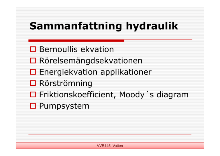
Sammanfattning hydraulik
advertisement

Sammanfattning hydraulik Bernoullis ekvation Rörelsemängdsekvationen Energiekvation applikationer Rörströmning Friktionskoefficient, Moody´s diagram Pumpsystem VVR145 Vatten BERNOULLI’S EQUATION p V 2 2g z H const . Bernoulli’s equation is a useful relationship between pressure, p, velocity, V, and geometric height, z, above a reference plane (datum). H: energy head (m) z: elevation head above datum (m) V: velocity (m/s) g: gravity acceleration (m/s2) p: pressure (Pa) γ: weight density for the flowing fluid (N/m3) Quantity Name Measure of H Energinivå Total energi P/γ Tyckhöjd “tryckenergi” Z Geometrisk höjd Lägesenergi V2/(2g) Hastighetshöjd Rörelseenergi p z piezometri c head or H .G.L Hydraulic Grade Line =>Trycknivå VVR145 Vatten γ=w=ρg Grundläggande ekvationer Pitotrör (manometri, peizometer) Ångtryck, kavitation Energi- och trycklinjer Strömning med energiförlust Bernoullis ekvation (K.E.; B.E.; E.E.) VVR145 Vatten Momentum Equation (RRM ekv.) FX Q ( VX ,OUT VX , IN ) ( x direction) FY Q ( VY ,OUT VY , IN ) ( y direction) FZ Q ( VZ ,OUT VZ , IN ) F: : Q: VOUT: VIN: : ( z direction) Sum of all external forces acting on the control volume (like the streamtube). Density of fluid Flowrate Velocity out of the control volume Velocity in to the control volume Correction coefficient for momentum (non-uniform velocity) VVR145 Vatten Methodology Using The Momentum Equation For A Fluid Flow Problem 1. Define an appropriate control volume (Draw picture) 2. Define coordinate axes (For F and V ; find out + and -) 3. Determine all forces (magnitude and direction) acting on the control volume (Draw picture) 4. Determine flowrate, outflow and inflow velocities to the control volume (if not given, use continuity equation and Energy / Bernoulli equation) 5. Solve momentum equation: ΣF = ρQ(V2 - V1) = Total forces acting on CV VVR145 Vatten Rörströmning I--IV Energiförluster vid rörströmning Lokala energiförluster Seriekopplade rörledningar Parallellkopplade rörledningar Trereservoirproblemet Allmänfriktionslag Turbulent rörströmning Friktionskoefficient, Moody´s diagram Icke-cirkulära rör VVR145 Vatten (total energi) (trycknivå) VVR145 Vatten Bell-mouth = Trattformig Pipe systems – branched pipe systems J Solution 3 Possible flow situations: 1) From reservoir 1 and 2 to reservoir 3 2) From reservoir 1 to reservoir 2 and 3 3) From reservoir 1 to 3 (Q2 = 0) For the situation as shown: Energy equation HJ = PJ/w + zJ + V2J/2g hf1 + hlocal,1 = z1 – HJ hf2 + hlocal,2 = z2 – HJ hf3 + hlocal,3 = HJ – z3 Continuity equation Q3 = Q1 + Q2 As HJ (HJ is total head at J) is initially unknown, a method of solution is as follows: 1) Guess HJ 2) Calculate Q1, Q2, and Q3 3) If Q1 + Q2 = Q3, then the solution is correct 4) If Q1 + Q2 ≠ Q3, then return to 1). Ett vattenflöde på 60 l/s strömmar genom rörledningen i Figur 2.5 a) Om vattnet stiger 3.0 m ovan rörets centrum i Pitot-röret vid B, hur högt stiger vattnet i piezometern vid A? a) Hur stort är det statiska trycket (i Pa) vid rörcentrum i B? Försumma alla energiförluster. + 3.0 m Figur 2.5 VVR145 Vatten Vad är skillnad mellan A o B? p V w z 2 g H konst. A 2 VVR145 Vatten I figuren visas en Venturimeter (flödesmätare). Vilket vattenflöde går genom rörledningen för det aktuella differentialmanometerutslaget i ledningen? Relativa densiteten för kvicksilver är SHg = 13.56. Försumma eventuella förluster mellan 1 och 2. VVR145 Vatten 2.5 En vattenstråle avbördas med ett konstant flöde av 35 l/s från den övre tanken, se figuren nedan. Om jetdiametern vid sektion 1 är 10 cm, vilka krafter mäts av vågarna vid A och B. Anta att en tom tank väger 135 kg och att tankens ytarea är 0.4 m2. H = 3 m och h = 0.3 m. VVR145 Vatten 1 z V t g t2 z0 2 V V g t z z0 VVR145 Vatten (Based on Cast Parable) I37: This corrugated ramp is used as an energy dissipator in a twodimensional open channel flow. For a flowrate of 5.4 m3/(sm) calculate the head lost, the power dissipated, and the horizontal component of force exerted by the water on the ramp. 2 X 1 VVR145 Vatten The hydraulic characteristics for the pipe system, Hsyst, is obtained from the energy equation L Q2 H z h z f syst losses D 2 gA 2 (local losses neglected in this case) Hsyst states how much energy that is needed to transport 1 kg of water from A to B Hp states how much energy the pump can provide to the water When the pump is introduced in the pipe system the flowrate and pump head will adjust so that Hsyst = Hp Hsyst: Systemkurvan består av skillnad i nivå + friktionsförluster VVR145 Vatten PARALLEL PUMPING To deal with cases where you have pumps operating in parallel you can consider them as being replaced by a fictive equivalent pump with a pump curve obtained by horizontal addition of the single pumps pump curves VVR145 Vatten Horisontal addition PUMPS IN SERIES To deal with cases where you have pumps operating in series you can consider them as being replaced by a fictive equivalent pump with a pump curve obtained by vertical addition of the single pumps pump curves VVR145 Vatten Vertical addition J30: Water (20C) is pumped between two reservoirs through two identical, parallel pipes each with a diameter of 0.2 m, length 1000 m, and equivalent sand roughness of 410-4 m. a) What flow is expected through the pump? b) How much energy (kWh) is needed to pump 1 m3 of water? The efficiency of the pump η = 0.75 VVR145 Vatten VVR145 Vatten


