Teacher`s powerpoint presentation
advertisement
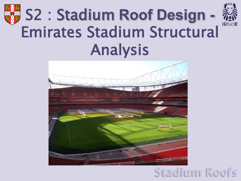
S2 : Stadium Roof Design Emirates Stadium Structural Analysis Cut out Model In order to understand the loading on the Primary Girder assemble the 3D model of the Emirates Stadium Roof. 1. Locate the pieces with slot number 1. 2. Cut around the black lines leaving the slots till last. 3. Slot the pieces together and repeat for slots up until number 33. 4. Once all the girders are connected, assemble the outer ring. 5. Put the structure in place and, working in one direction around the ring, secure the structure in place. P16 Tension Forces Applying a tension force to a ruler has the effect of pulling the two ends further apart. The tension force causes the ruler to stretch and straighten. If the ruler was made out of a different material, such as a metal, ceramic or composite it would behave differently depending on the strength of that material. String is strong in tension and needs an extremely high force to get it to break. However if you separate a single strand and pull either end it breaks easily. By increasing the cross-sectional area of the string by using lots of strands the string can take a larger tensile force. So Tension force is proportional to cross-sectional area and material strength The material property for strength is called yield strength σy P17 Tension = A x σy Compression Forces Applying a compression force attempts to push the ends of the ruler closer together. When enough force is applied, the ruler will deform out of the plane in which the force is acting. This deformation behaviour is known as buckling A shorter ruler will require a greater compressive load to get it to buckle So longer components are more likely to fail by buckling than shorter ones. P18 Moments A force applied to the free end of a ruler resting on the edge of a table will cause the ruler to rotate about the edge of the table. If the ruler is “fixed” to the table with a hand, the force applied to the free end will cause the ruler to bend as it cannot rotate anymore. The force causes the ruler to deform because it has created a “bending moment” in the ruler. If you apply a greater force you get a greater deflection, so the bending moment experienced by the ruler must also be larger. If the length of the overhanging ruler is increased and the same force is applied the deformation will be greater, so the bending moment created must also be greater. Moment is proportional to Force and Distance Moment = Force x Perpendicular distance P19 Couples If laid flat on a table the ruler will rotate if two equal forces in opposite directions are applied to either end. “Fixing” the ruler in the centre with a hand prevents the rotation, so when the forces are applied bending moments are set up in the ruler causing it to deform. Looking at the equilibrium of the ruler shows that the two forces must be equal, F1 = F2 = F F1 pivot This sort of moment is called a Couple (C). If the forces act a distance d apart we get C = F1 x d/2 + F2 x d/2 = (F1 + F2) x d/2 = (F + F) x d/2 = 2F x d/2 P20 =Fxd d/2 d/2 F2 Roof Loads Roof Load on Tertiary Girders = Roof covering (opaque and transparent) + Elemental loads (Wind, Rain and Snow) + Lighting and sound = 65kN/m Transparent roof covering to let in light to the grass pitch Opaque roof covering providing shelter from wind, rain and snow P21 Playing surface Load Path Tertiary girders support the roof load. Tertiary girders transfer load to secondary girders. Tertiary girders transfer load to primary girders. Secondary girders transfer load to primary girders. P22 Free body diagram of Primary Girder A “free body diagram” will show magnitude and direction of all forces acting on the primary girder. There are 10 Tertiary girders loading the Primary girder The Secondary girders transfer an additional load, from T6, T7 and T8. R T1 + Secondary T2 T3 T4 T5 T5 T4 T3 T1 T2 + Secondary R All these forces act downwards, so there must be a reaction force from the Tripods it sits on to keep the girder in equilibrium. P23 Cutting the structure The magnitude and type of the internal forces in the Primary Girder will determine how much steel is required to withstand these forces. It’s also important to locate where these forces will be the greatest in the structure. Having identified the position of interest, say the half way point, the girder needs to be “cut” at this point in order to calculate the internal forces acting here. M R T1 + T2 Secondary T3 T4 T5 If the structure was cut for real, the structure would rotate about a pivot at the tripod support. So the missing internal force must be a moment. P24 This can be calculated by considering moment equilibrium at this point. Moment into tension and compression We know the girder will be made out of steel circular tubes, one on top and one on the bottom a distance d (m) apart which can be measured from the model. Cross-section d (m) M The forces in the tubes must be either tension or compression, so M must be carried inside the structure as a couple. T C C T Couple M = T x d or M = C x d P25 Compression force in the top tube and tension in the bottom tube gives the correct anti-clockwise direction of rotation. Steel tube in tension Steel can withstand a stress of 325N/mm2 before it breaks in tension. So to find the required cross-sectional area we can use:- Tension Force = σy x Cross-sectional Area Cross-Sectional Area required (in mm) = Tension Force 325 We know that the thickness of tube (t) to be used is 40mm r Cross-sectional Area = Circumference x thickness t P26 So we can evaluate the required Radius r Steel tube in Compression The compression tube will also require the cross-sectional area of the tension tube: however, the buckling that it will undergo needs to be limited as this will also cause a catastrophic failure. Two straws threaded at either end on a cocktail stick will behave in the same way as the two tubes when put under a bending moment. Out of plane deformation Buckling failure The green straw is in tension and stretches in the same direction as the force The yellow straw is in compression and “buckles” or deforms out of plane eventually failing at a relatively low force. To resist this out of plane movement of the yellow straw a triangular crosssectional is used to resist this out of plane movement. Compression girder Additional Struts Resisting out of plane movement P27 Two Tension Girders Cross-section Actual Design Additional struts for bracing www.cidect.com P28
