ppt
advertisement

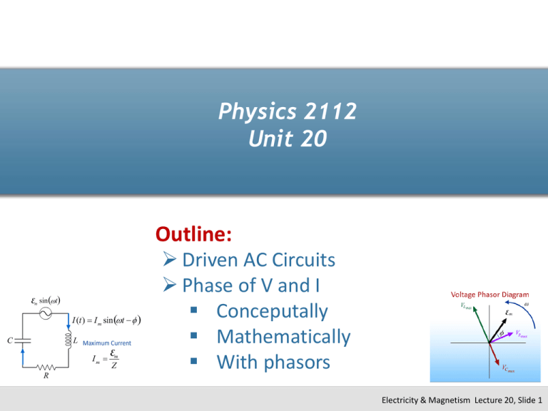
Physics 2112 Unit 20 Outline: Driven AC Circuits Phase of V and I Conceputally Mathematically With phasors Electricity & Magnetism Lecture 20, Slide 1 AC Generator e = Vmaxsin(wdt) Driving frequency = natural frequency (wo) Electricity & Magnetism Lecture 20, Slide 2 “Phase” between I and V Simple Case - Resistors IR = VR/R R Voltage goes up current goes up “In phase” Phase angle = 0o I= Vmax/R sin(wdt) Amplitude = Vmax/R Electricity & Magnetism Lecture 20, Slide 3 Capacitors Q = CV = CVmaxsin(wt) C I = VmaxwC cos(wt) 90o Amplitude = Vmax/XC where XC = 1/wC is like the “resistance” of the capacitor XC depends on w Unit 20, Slide 4 Inductors dI L = VL = Vmax sin(wt ) dt L Vmax I = cos(wt ) wL 90o Amplitude = Vmax/XL where XL = wL is like the “resistance” of the inductor XL depends on w Electricity & Magnetism Lecture 20, Slide 5 Phase Summary R Vmax I= sin(wd t ) R C I = Vmax Cw cos(wd t ) Vmax = sin(wd t 90o ) C L Vmax I = cos( wt ) wL Vmax = sin(wt 90o ) L V and I “in phase” I “leads” V I “lags” V “ELI the ICE man” Electricity & Magnetism Lecture 20, Slide 6 What does this look like together? Notice phase relationships Electricity & Magnetism Lecture 20, Slide 7 What does this look like together? Capacitor and Inductor always 180o out of phase Capacitor/Inductor and Resistor always 90o out of phase Resistor is some unknown phase angle out of phase is signal generator Electricity & Magnetism Lecture 20, Slide 8 What about current? Current is always the same through all elements (in series) Current and Voltage in phase across Resistor Current and voltage out of phase by unknown phase angle across signal generator (We’ll find this “phase angle” later.) Electricity & Magnetism Lecture 20, Slide 9 Reactance Summary R R C 1 XC = wC L X L = Lw Doesn’t depend on w w goes up, c goes down w goes up, L goes up Electricity & Magnetism Lecture 20, Slide 10 Example 20.1 (Inductor Reactance) L A 60Hz signal with a Vmax = 5V is sent through a 50mH inductor. What is the maximum current, Imax, through the inductor? Electricity & Magnetism Lecture 20, Slide 11 Phasors Think of same material graphically using “phasors” Phasor just thinks of sine wave as rotating vector Electricity & Magnetism Lecture 20, Slide 12 Circuit using Phasors Represent voltage drops across elements as rotating vectors (phasors) Imax XL VL and VC 180o out of phase VL and VR 90o out of phase Remember VR and I in phase Imax R Imax XC Electricity & Magnetism Lecture 20, Slide 13 Make this Simpler Imax XC C emax = Imax Z f emax L Imax(XL XC) Imax XL R Imax R Imax R Z = R 2 ( X L X C )2 R Impedance Triangle X L XC tan (f ) = R Electricity & Magnetism Lecture 20, Slide 14 Summary Imax XC VCmax = Imax XC VLmax = Imax XL VRmax = Imax R emax C emax L Imax XL R = Imax Z Imax R Imax = emax / Z Z = R 2 ( X L X C )2 Z= R 2 2 X L XC X L XC tan (f ) = R f R Electricity & Magnetism Lecture 20, Slide 15 CheckPoint 1(A) A RL circuit is driven by an AC generator as shown in the figure. The voltages across the resistor and generator are. A. always out of phase B. always in phase C. sometimes in phase and sometimes out of phase Electricity & Magnetism Lecture 20, Slide 16 CheckPoint 1(B) A RL circuit is driven by an AC generator as shown in the figure. The voltages across the resistor and inductor are. A. always out of phase B. always in phase C. sometimes in phase and sometimes out of phase Electricity & Magnetism Lecture 20, Slide 17 CheckPoint 1(C) A RL circuit is driven by an AC generator as shown in the figure. The phase difference between the CURRENT through the resistor and inductor A. is always zero B. is always 90o C. depends on the value of L and R D. depends on L, R and the generator voltage Electricity & Magnetism Lecture 20, Slide 18 Example 20.2 (LCR) In the circuit to the right • L=500mH • Vmax = 6V • C=47uF • R=100W V C L R What is the maximum current and phase angle if w = 60rad/sec? What is the maximum current and phase angle if w = 400 rad/sec? What is the maximum current and phase angle if w = 206 rad/sec? Electricity & Magnetism Lecture 20, Slide 19 What does this look like graphically? Electricity & Magnetism Lecture 20, Slide 20 Point of confusion?? VL + VC + VR + e = 0 VL-max + VC-max + VR-max + e = 0 (Add like vectors) I max Vmax = Z I V Z (Imax and Vmax happen at different times.) Electricity & Magnetism Lecture 20, Slide 21 CheckPoint 2(A) A driven RLC circuit is represented by the phasor diagram to the right. The vertical axis of the phasor diagram represents voltage. When the current through the circuit is maximum, what is the potential difference across the inductor? A. VL = 0 B. VL = VL-max/2 C. VL = VL=max CheckPoint 2(B) A driven RLC circuit is represented by the above phasor diagram. When the capacitor is fully charged, what is the magnitude of the voltage across the inductor? A. VL = 0 B. VL = VL-max/2 C. VL = VL=max Electricity & Magnetism Lecture 20, Slide 23 CheckPoint 2(C) A driven RLC circuit is represented by the above phasor diagram. When the voltage across the capacitor is at its positive maximum, VC = +VC-max, what is the magnitude of the voltage across the inductor? A. VL = 0 B. VL = VL-max/2 C. VL = VL=max Electricity & Magnetism Lecture 20, Slide 24 Example 20.3 Consider the harmonically driven series LCR circuit shown. Vmax = 100 V Imax = 2 mA VCmax = 113 V The current leads generator voltage by 45o L and R are unknown. C V ~ L R What is XL, the reactance of the inductor, at this frequency? Conceptual Analysis The maximum voltage for each component is related to its reactance and to the maximum current. The impedance triangle determines the relationship between the maximum voltages for the components Strategic Analysis Use Vmax and Imax to determine Z Use impedance triangle to determine R Use VCmax and impedance triangle to determine XL Electricity & Magnetism Lecture 20, Slide 25


