Flow Distortion in a 3
advertisement

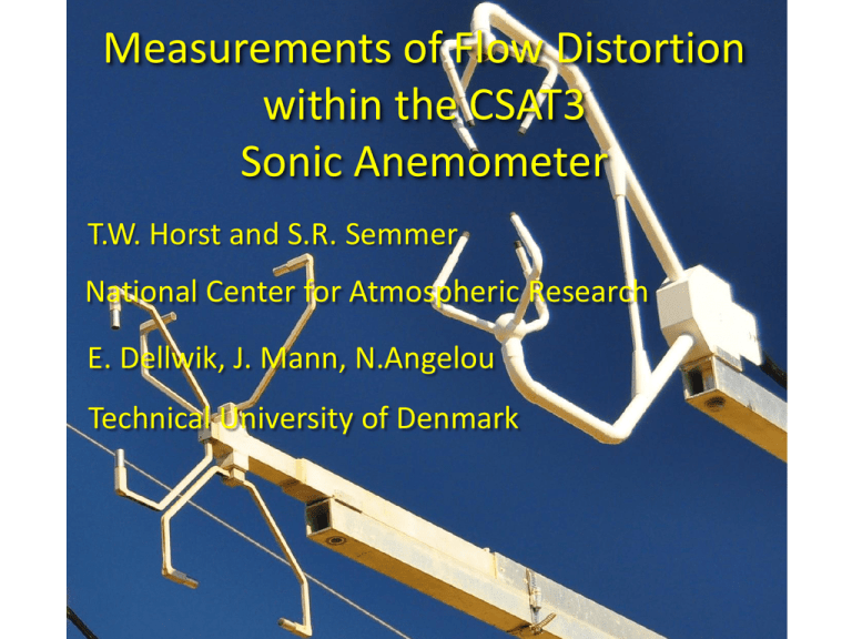
Measurements of Flow Distortion within the CSAT3 Sonic Anemometer T.W. Horst and S.R. Semmer National Center for Atmospheric Research E. Dellwik, J. Mann, N.Angelou Technical University of Denmark Measurements of Flow Distortion within the CSAT3 Sonic Anemometer • History of Sonic Development Measurements of Flow Distortion within the CSAT3 Sonic Anemometer • History of Sonic Development • CSAT 3 Transducer Shadowing Measurements of Flow Distortion within the CSAT3 Sonic Anemometer • History of Sonic Development • CSAT 3 Transducer Shadowing • Field Tests of Transducer Shadowing • NCAR Comparison to ATI-K sonics Measurements of Flow Distortion within the CSAT3 Sonic Anemometer • History of Sonic Development • CSAT 3 Transducer Shadowing • Field Tests of Transducer Shadowing • NCAR Comparison to ATI-K sonics • DTU Comparison to Doppler LiDAR Hamilton, New York 1. Introduction Chandran Kaimal Credit for the first sonic anemometer should be given to Carrier and Carlson (Croft Laboratories, Harvard University), who in 1944 nd beyond recovery. He had brought with him ideas proach. These ideas were provided by Peter Schofer, Kaimal-designed sonic anemometers with dedicated vertical paths ble range in the signals ls could then hat could be prototype, but my table and be sharp s accurate U. and s my thesis advisor. Figure 1a of Washington, 1960 ed by the atmospheric physics group at the Hanford h scattered sage brush 1 m high. A 125-m high tower ometer probe was mounted on a short mast with its t and 0.5 m for the second. nd beyond recovery. He had brought with him ideas proach. These ideas were provided by Peter Schofer, Kaimal-designed sonic anemometers with dedicated vertical paths ble range in the signals ls could then hat could be prototype, but my table and be sharp s accurate U. and s my thesis advisor. Figure 1a of Washington, 1960 ed by the atmospheric physics group at the Hanford h scattered sage brush 1 m high. A 125-m high tower ometer probe was mounted on a short mast with its t and 0.5 m for the second. AFCRL/EG&G, 1973 BAO/ATI, 1990 nd beyond recovery. He had brought with him ideas proach. These ideas were provided by Peter Schofer, Kaimal-designed sonic anemometers with dedicated vertical paths ble range in the signals ls could then hat could be prototype, but my table and be sharp s accurate U. and s my thesis advisor. Figure 1a of Washington, 1960 ed by the atmospheric physics group at the Hanford h scattered sage brush 1 m high. A 125-m high tower ometer probe was mounted on a short mast with its t and 0.5 m for the second. BAO/ATI, 1990 Kaimal (1979): Horizontal paths require correction for transducer wakes Impinging on the acoustic paths AFCRL/EG&G, 1973 Transducer shadowing depends on wind direction w.r.t. path and d/L (Kaimal, 1979) University of Washington non-orthogonal sonic anemometer, Businger and Oncley (1984) CSAT3 Geometry and Coordinates CSAT3 Transducer Shadowing, L/d = 18, d/L = 0.056 0.97 Vertical velocity statistics, such as <w’w’> and <w’Ts’>, are measured to be greater with a vertical-path sonic than with a non-orthogonal sonic. Vertical velocity statistics, such as <w’w’> and <w’Ts’>, are measured to be greater with a vertical-path sonic than with a non-orthogonal sonic. CSAT3 transducer shadowing? CSAT3 Transducer Shadowing, L/d = 18, d/L = 0.056 0.16 18 + CSAT3 transducer shadowing measured in the NCAR wind tunnel Marshall-2012 sonic anemometer field test 5 sonics at 3m height, 0.5 m spacing CSAT.x (test sonic) ATI-K.e CSAT.w CSAT.va ATI-K.w (reference) (vertical a-path) (reference) (test sonic) CSAT3 intercomparison with 3-component DOPPLER LiDAR E. Dellwik, J. Mann, N. Angelou, E. Simley, M. Sjoholm & T. Mikkelsen, Technical University of Denmark Technical University of Denmark Risø Wind Scanner Experiment November, 2013 Inside Outside o α o α LiDARs focused Inside sonic measurement volume u, v, w LiDARs focused 80 cm Outside of sonic u, v, w Thin lines: Sonic; Thick lines, LiDAR (60 Hz data) Two possible causes for sonic flow distortion 1. Transducer shadowing: Wakes behind transducers. 2. Blocking of flow: Flow speeds up within sonic. • Strong dependence on wind direction. • Weak dependence on wind direction. Two possible causes for sonic flow distortion 1. Transducer shadowing: Wakes behind transducers. 2. Blocking of flow: Flow speeds up within sonic. • Strong dependence on wind direction. • Weak dependence on wind direction. • Maximum effect near transducers. • Maximum effect near center of sonic array. Two possible causes for sonic flow distortion 1. Transducer shadowing: Wakes behind transducers. 2. Blocking of flow: Flow speeds up within sonic. • Strong dependence on wind direction. • Weak dependence on wind direction. • Maximum effect near transducers. • Maximum effect near center of sonic array. • LiDAR and sonic data differ for the Inside case. • LiDAR and sonic data agree for Inside case. Two possible causes for sonic flow distortion 1. Transducer shadowing: Wakes behind transducers. 2. Blocking of flow: Flow speeds up within sonic. • Strong dependence on wind direction. • Weak dependence on wind direction. • Maximum effect near transducers. • Maximum effect near center of sonic array. • LiDAR and sonic data differ for the Inside case. • LiDAR and sonic data agree for Inside case. • USonic/ULiDAR are the same for Inside and Outside cases. • USonic/ULiDAR are different for Inside and Outside cases. Outside case: k = USonic/ULiDAR , U = UZ 1.05 k = Usonic/Ulidar 1 0.95 0.9 uz 0.85 −50 0 50 100 Wind direction on sonic [°] 150 Outside case: k = USonic/ULiDar , U = UX,Y 1.05 k = Usonic/Ulidar 1 0.95 0.9 u x uy 0.85 −50 0 50 100 Wind direction on sonic [°] 150 Two possible causes for sonic flow distortion 1. Transducer shadowing: Wakes behind transducers. 2. Blocking of flow: Flow speeds up within sonic. Strong dependence on wind direction. • Weak dependence on wind direction. • LiDAR and sonic data differ for the Inside case. • LiDAR and sonic data agree for Inside case. • Maximum effect near transducers. • Maximum effect near center of sonic array. • USonic/ULiDAR are the same for Inside and Outside cases. • USonic/ULiDAR are different for Inside and Outside cases. Comparison between Inside and Outside cases, U = UZ 1.05 k = Usonic/Ulidar 1 0.95 0.9 uz 0.85 −50 0 50 100 Wind direction on sonic [°] 150 Comparison between Inside and Outside cases, U = UX,Y 1.05 k = Usonic/Ulidar 1 0.95 0.9 u x uy 0.85 −50 0 50 100 Wind direction on sonic [°] 150 Two possible causes for sonic flow distortion 1. Transducer shadowing: Wakes behind transducers. 2. Blocking of flow: Flow speeds up within sonic. Strong dependence on wind direction. • Weak dependence on wind direction. LiDAR and sonic data differ for the Inside case. • LiDAR and sonic data agree for Inside case. • Maximum effect near transducers. • Maximum effect near center of sonic array. • USonic/ULiDAR are the same for Inside and Outside cases. • USonic/ULiDAR are different for Inside and Outside cases. Two possible causes for sonic flow distortion 1. Transducer shadowing: Wakes behind transducers. 2. Blocking of flow: Flow speeds up within sonic. Strong dependence on wind direction. • Weak dependence on wind direction. LiDAR and sonic data differ for the Inside case. • LiDAR and sonic data agree for Inside case. Maximum effect near transducers. • Maximum effect near center of sonic array. • USonic/ULiDAR are the same for Inside and Outside cases. • USonic/ULiDAR are different for Inside and Outside cases. Two possible causes for sonic flow distortion 1. Transducer shadowing: Wakes behind transducers. 2. Blocking of flow: Flow speeds up within sonic. Strong dependence on wind direction. • Weak dependence on wind direction. LiDAR and sonic data differ for the Inside case. • LiDAR and sonic data agree for Inside case. Maximum effect near transducers. • Maximum effect near center of sonic array. USonic/ULiDAR are the same for Inside and Outside cases. • USonic/ULiDAR are different for Inside and Outside cases. Two possible causes for sonic flow distortion Transducer shadowing: Wakes behind transducers. 2. Blocking of flow: Flow speeds up within sonic. Strong dependence on wind direction. • Weak dependence on wind direction. LiDAR and sonic data differ for the Inside case. • LiDAR and sonic data agree for Inside case. Maximum effect near transducers. • Maximum effect near center of sonic array. USonic/ULiDAR are the same for Inside and Outside cases. • USonic/ULiDAR are different for Inside and Outside cases. • Analysis is continuing of the DTU Wind Scanner/CSAT3 data, with the goal of directly measuring the sonic anemometer flow distortion/transducer shadowing. • Analysis is continuing of the DTU Wind Scanner/CSAT3 data, with the goal of directly measuring the sonic anemometer flow distortion/transducer shadowing. • Results of the NCAR data analysis will be published in an upcoming issue of Boundary Layer Meteorology: Horst, T.W., S.R. Semmer and G. Maclean, Correction of a Non-Orthogonal, Three-Component Sonic Anemometer for Flow Distortion by Transducer Shadowing, Accepted, with minor revision, for publication in Boundary Layer Meteorology.


