Thermally-driven desalination systems
advertisement
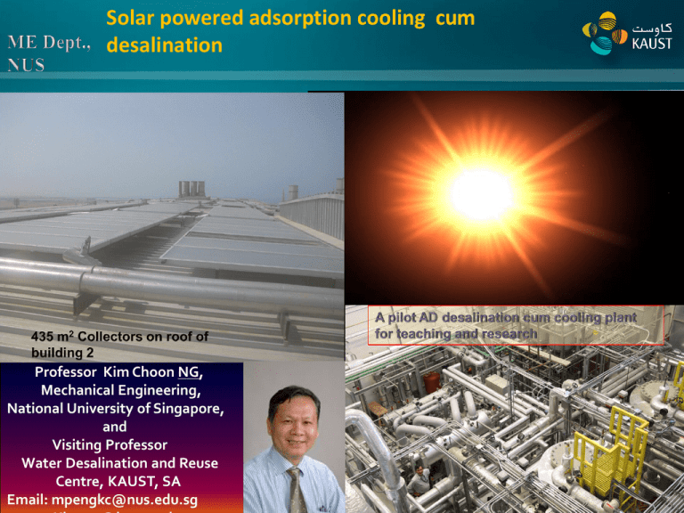
Solar powered adsorption cooling cum desalination Professor Kim Choon NG, Mechanical Engineering, National University of Singapore, and Visiting Professor Water Desalination and Reuse Centre, KAUST, SA Email: mpengkc@nus.edu.sg Adsorption-triggered-evaporation 28-36°C 12-33°C 7-28°C Cooling power, Tchilled = 720°C, 25- 32 Rtons/tonne 25-33°C Desorption-activated-condensation 45-75°C 28-33°C 25-30°C Mesoporous adsorbent SiO3.nH2 O , Potable water TDS 800m2/g <10ppm, pH =7.3,±0.1 5 to 12 m3/tonne.day 55-85°C, from Solar or waste heat Advantages: -Produce two useful effects with low-temperature heat input, -low specific energy (electric) consumption (1.38kWh/m3), -no major moving part, inexpensive materials for construction • The daily average radiation in Thuwal (KAUST) is about 22 MJ/m2.day (latitude λ=22o , sunshine hours from 9 to 13 h/day) • Estimated thermal rating is 1300 kWh/m 2.year, as compared with 925 kWh/m 2.year @ 65o C in Singapore . • Recommend to use tube collectors because (i) it is easy to handle, (ii) it reduces the dust accumulation – dust particles will slide over the tube curvature whilst those accumulated on top could be blown over by strong wind. Provide shading that reduces heat stress in green houses. 5 Why Co-Generation ? Conventional approach Primary fuel Electricity from grid (th 0.42 ) diesel “Kettle” Boiler (8 bar) electricity Electricallyoperated decicant dehumidifier DARI’s energy needs Electricity (- max at 1.3 MW) Co-generation cum solar Primary fuel, (Town gas) Gas Turbines x 2 units of 700 kW 375 to 500oC Steam (4800 kg/h) • Cooling (7o C and 15-18 0C) • Water (5 l/m2 .day) Waste heat operated boiler (8 bar) Steam driven AB/AD chillers Temperature cascaded utilization of exhaust energy with AB_AD chillers 125o C Conventional EUF=0.52 TriGen EUF =0.85 - Thermally-driven design Exhaust Gas Grid of KAUST Electric chillers (400 Rtons) CWS =7 C 500-600 kW for use in DARI 360 kW 1000 to 1200 kW 50-60 kW Gas Turbines (2x 700 kW) Steam (177 C, 8.3 bar) Further waste heat recovery 40 – 55 kW Exhaust leaving at < 125 C AB chillers (COP 0.9 to 1.1) giving 800 to 1000 Rtons CWS = 9-10 C 20 to 25 kW AD Chillers (COP =0.5 to 0.65) giving 120 to 150 Rtons CWS = 14 to 18 C Water production 75 m /day Seawater Cooling Towers (1200 Rtons) 7 Sea water feeding line Sea Water Tank Pre-treatment sea water tank 8 Release Valve Condenser Collection tank Condensate drainage Reactor Bed 9 Condenser Cooling water system and evaporator valves 11 Sea water Silo-type adsorber-desorber beds E x haust gas 2 0 0 to 25 0 C Post treatme nt tank Hot water storage Pretreatment tank Fresh water storage Waste heat recovery from exhaust Can the AD cycle scale to a commercial size ? – to work closely with industry partners of KAUST 4 Condenser 2 3 5 H Reaction bed tower Purified water storage tank Reaction bed tower Evaporator 1 d d 12 14 15
