Tandem Pumping
advertisement
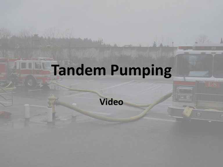
Tandem Pumping Video INITIAL SIZE-UP • When approaching the structure note the location of the FDC, Hydrant and Building Access. POSITIONING APPARATUS • When spotting the apparatus for access to the FDC ensure the hose lines will not impede access to the building and angle the apparatus to protect the operator from traffic. CONNECTING TO THE FDC • The Firefighter stretches the initial line to the FDC, connects the line and removes all caps. CONNECTING TO THE FDC • The Engineer connects the first line to the discharge and stretches the second line to the FDC. SECURING THE HOSELINES • After the hoses are connected to the apparatus and the FDC, prior to charging the lines, the Engineer straightens out the hoses to remove any kinks and keep the access to the building free of obstruction. The Engineer then secures the ends of the hose lines to the apparatus and the FDC. Any couplings will have the hoses secured within 10’ on both sides. • A kit containing four rope loops, four tie ropes two lanyards with clips and a red 2 ½” discharge cap that has a vent hole drilled in it will be issued to each apparatus. SECURING THE HOSELINES • The hoses at the pump panel are secured using a Lanyard with a loop on one end and a clip on the other. The Lanyard is secured to the pump by wrapping it around a discharge or intake and running the clip end through the loop. It is secured to the hoses using a loop of rope placed around the hose in a hose knot and attached to the clip. SECURING THE HOSELINES • The hoses are then secured to the FDC with the Lanyard and two rope loops. SECURING THE HOSELINES • If there are couplings between the pump panel and the FDC a rope will be used to secure the hoses with 10’ on both sides of the coupling. Lay the rope under the hoses, make a round turn on each side and secure with a square knot. SECURING THE HOSELINES • Once the hoses are secured the area surrounding the hoses must be secured from access by civilians or firefighters due to the high pressures. Secure an area 25’ on each side of the hoses with Caution or Danger tape. CAPPING THE INTAKE RELIEF VALVE (2006 PIERCE SHOWN) • Prior to establishing a supply, cap the Front Suction Intake Relief Valve on 2006 Pierce and the Pump Intake Relief Valve on H&W’s. A cap equipped with a vent hole or bleeder valve must be used. SUPPLY • The Third In Engine will connect to the FDC and the Fourth In Engine will supply the Tandem Pumping Evolution through the front suction. All hose lines and connections are to be away from the Engineers. SUPPLY • The Fourth In Engine establishes a supply and charges the line to the third In Engine with the pump at idle. • The Third In Engine opens the intake and then the discharges to the FDC. Remember to close the tank to pump valve and crack open the tank fill to bypass 30 - 50 GPM. SECOND SUPPLY • If the Third In Engine must establish a supply prior to the Fourth In Engine arrival a side suction must be used. SECOND SUPPLY • When the Fourth In Engine arrives it will supply the Third In Engine. The Third In Engineer will attach the 5” supply hose to the front suction. SECOND SUPPLY • The Fourth In Engine will connect the 5” supply for the Third In Engine to the large diameter discharge on the right side of the apparatus. Once a supply is established the line will be filled with the pump at idle. • After the discharge valve is open inform the Engineer of the Third In Engine the supply is ready. SECOND SUPPLY • Once the supply from the Fourth In Engine is established the Third In Engine Engineer will: • Bleed all air from the intake. • Slowly open the intake. • Close the first supply. • Confirm with the Engineer of the Fourth In Engine they are ready for Tandem Pumping. • The Fourth In Engine Engineer will then raise the pump pressure to 200 PSI

